Integrated hydroelectric power-generating system and energy storage device

a hydroelectric power-generating system and energy storage technology, applied in the direction of electric generator control, renewable energy generation, greenhouse gas reduction, etc., can solve the problems of insufficient return on of the static head in all other dams, the power level of the in-stream power-generating system is much smaller, and the cost of building the conventional equipment to generate the power is very high, so as to achieve the effect of efficient production of electricity

Active Publication Date: 2013-09-17
AMERICAN HYDRO JET CORP
View PDF17 Cites 15 Cited by
  • Summary
  • Abstract
  • Description
  • Claims
  • Application Information

AI Technical Summary

Benefits of technology

[0010]It is an object of this invention to provide a low-cost hydroelectric power-generating system which takes power from current in a waterway or coastal current that can efficiently produce electricity to economic benefit.
[0011]Another object of this invention is to produce a low-cost hydroelectric power-generating system that is fast and easy to install and service.
[0012]It is a further object of this invention to produce a low-cost hydroelectric power-generating system that permits applications that are conventionally not possible because of:

Problems solved by technology

The static head in all other dams was not sufficient to provide a return-on-investment for a conventional hydroelectric power plant in conjunction with these dams.
However, the power level of an in-stream power-generating system is much smaller than what can be generated by a static-head-type turbine as mentioned above.
Both low-static-head and in-stream systems have traditionally not attracted interest because the cost of building the conventional equipment to generate this power was very high in relation to the benefit of the power produced.
The presence of a float makes it vulnerable to debris, waves and ice in a waterway as well as adding cost.
It is submersible and can be suspended in a water current in ways that are not possible or practical with a separate turbine and generator.
Most conventional hydroelectric power generation systems do not have the capability of reversing the operation and turning the power generation system into a pumping system by applying an electric current to the generator.

Method used


Image

  • Integrated hydroelectric power-generating system and energy storage device
  • Integrated hydroelectric power-generating system and energy storage device
  • Integrated hydroelectric power-generating system and energy storage device

Examples


Embodiment Construction

[0107]While the principles of this invention have been described in connection with specific embodiments, it should be understood clearly that these descriptions are made only by way of example and are not intended to limit the scope of the invention.

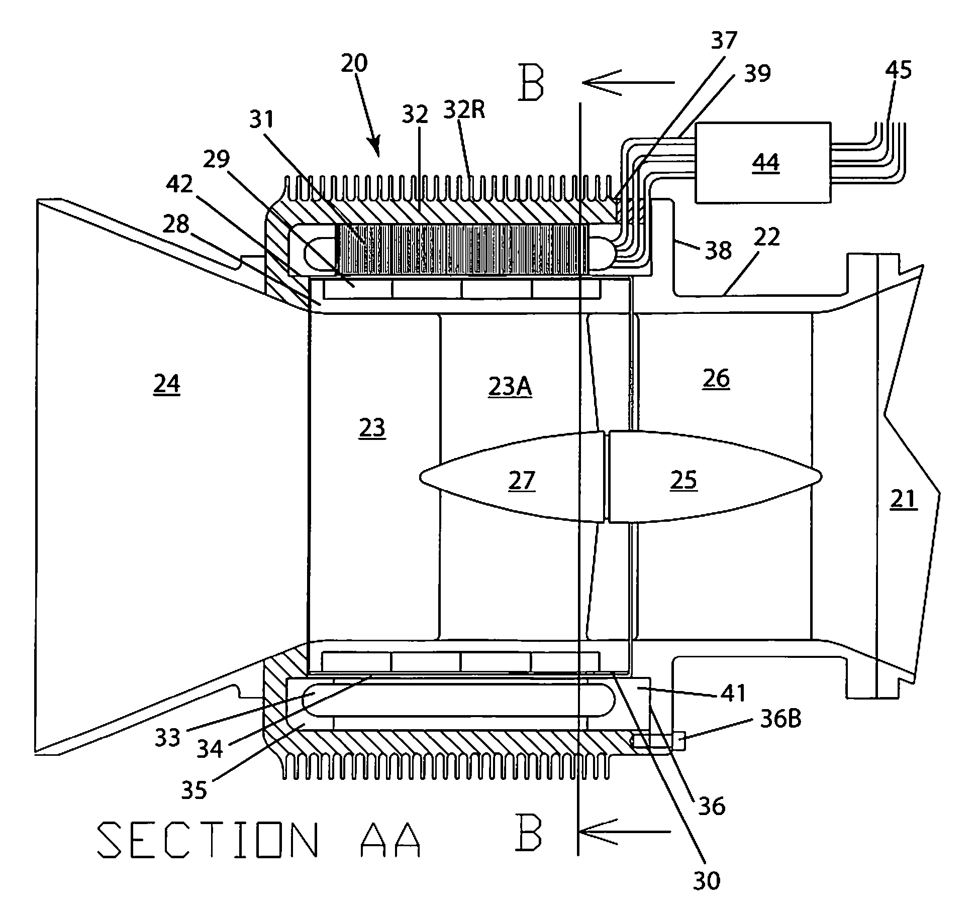
[0108]The following detailed specification explains a novel approach to hydroelectric power generation starting with the integration of turbine and generator. This inventive concept will permit the application of hydroelectric power generation previously impossible by allowing configurations of systems previously mechanically impossible and by drastically lowering cost of manufacture, installation and maintenance, making systems efficient that were previously economically not feasible.

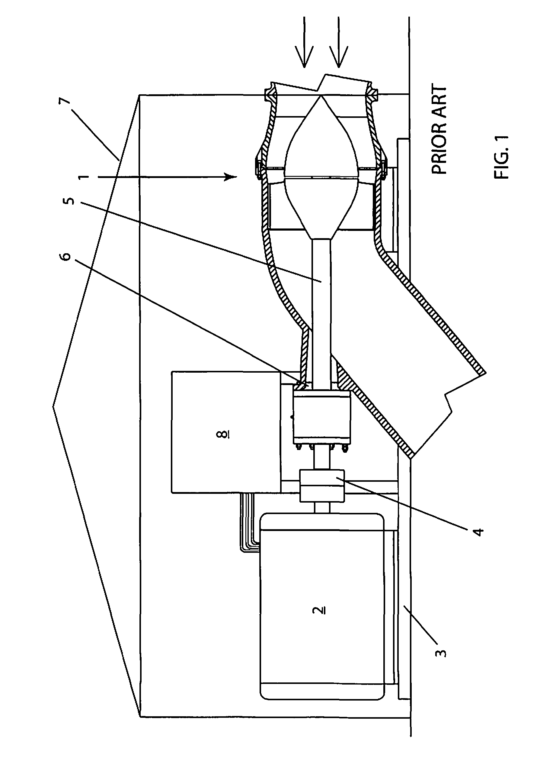
[0109]FIG. 1 (PRIOR ART) shows the conventional way of static-head hydroelectric power generation using a separate turbine 1 and generator 2 mounted on a common base 3 requiring a coupling 4, a shaft 5, and a shaft seal 6. Further, there is the necessity o...


PUM


Abstract

A hydroelectric power-generating apparatus comprising: (1) a fluid inlet, (2) a diffuser having (a) at least one vane supporting a diffuser hub and (b) a rotor rotatably supported by the diffuser hub and having (i) impeller blades, (ii) an impeller hub, and (iii) a shroud at the periphery of the rotor, the shroud including at least one magnet, and (3) a housing surrounding the shroud and having a rigidly-attached stator including laminations and at least one electrical coil, whereby a flow of fluid through the diffuser and rotor causes the rotation of the rotor and the at least one magnet induces an electric current in the at least one coil.

Description

RELATED APPLICATION[0001]This application claims the benefit on U.S. Provisional Application 61 / 146,182 filed on Jan. 21, 2009, the entire contents of which are incorporated herein by reference.FIELD OF THE INVENTION[0002]This invention relates to the low-cost generation of electrical power from waterways and coastal currents.BACKGROUND OF THE INVENTION[0003]Power generation from waterways and coastal currents is well-known and commonly practiced in coastal waters and rivers. A well-known application is in dams with built-in turbines driving generators for the production of electric power. Most navigable waterways have a controlled water level to facilitate shipping by maintaining minimum depths through the placement of dams in the waterway. Shipping is made possible through the location of locks adjacent to the dams.[0004]The Mississippi River is an example of such a waterway with a controlled water level and a system of dams with locks. The water drop at most dams is 20 feet or le...

Claims


Application Information

Patent Timeline
Patent Type & Authority Patents(United States)
IPC IPC(8): H02K7/18
CPCF03B3/04F03B3/18H02K7/1823Y02E10/223Y02E10/20
Inventor ROOS, PAUL W.
Owner AMERICAN HYDRO JET CORP
Why Eureka
Try Eureka