
Apparatus and method of obtaining field by measurement

a technology of three-dimensional field and apparatus, applied in the field of three-dimensional field obtaining apparatus, can solve the problems of difficult application, technique cannot be used as a common tool to analyze a magnetic field, apparatus can only perform observation of the surface, etc., and achieve the effect of high accuracy

Active Publication Date: 2013-09-17
KYOTO UNIV +1
View PDF11 Cites 18 Cited by
  • Summary
  • Abstract
  • Description
  • Claims
  • Application Information

AI Technical Summary

Benefits of technology

The present invention provides a technique for accurately obtaining a three-dimensional field of magnetic potential, electric potential, or other rest satisfying the Laplace equation from measured values taken in a non-contacting area. This technique can be applied to fields with at least two dimensions. The invention allows for accurate reproduction of the three-dimensional field through the calculation of a function based on the first and second measured values. The technical effects are improved accuracy in measuring magnetic and electric fields in non-contacting areas.

Problems solved by technology

However, these apparatuses can only perform observation of the surface of magnetic material which is extremely clean, and it is not easy to apply them as practicable evaluation apparatuses or inspection apparatuses provided in a manufacturing line.
However, when the measurement distance between the surface of the sample and the probe is too small, since affection of the van der Waals force between the surface of the sample and the probe becomes large and quantitative observation of the magnetic domain structure becomes difficult, it is absolutely necessary in the quantitative observation to separate the probe from the surface of the sample by a distance larger than or equal to a predetermined distance.
In the meantime, the technique proposed in the Document 1 premises that the current density distribution exists only on the surface of the sample, and the technique can not be used as a common tool to analyze a magnetic field.

Method used


Image

  • Apparatus and method of obtaining field by measurement
  • Apparatus and method of obtaining field by measurement
  • Apparatus and method of obtaining field by measurement

Examples


Embodiment Construction

[0038]First, discussion will be made on the principle of a three-dimensional field obtaining method in accordance with the present invention. Various three-dimensional scalar fields, for example, like a field of magnetic potential which a magnetized magnetic material forms at circumference thereof, a field of electric potential which a electric charge on an insulating material forms, a field of magnetic potential which the current flowing through inside of a multilayer semiconductor device forms at circumference or inside of the semiconductor device, and the rest, are formed at circumferences or insides of objects due to existence of the objects. These fields satisfy the Laplace equation, what the three-dimensional field obtaining method in accordance with the present invention obtains is the three-dimensional scalar field itself satisfying the Laplace equation or a function derived by differentiating the three-dimensional scalar field with respect to a predetermined direction one t...


PUM


Abstract

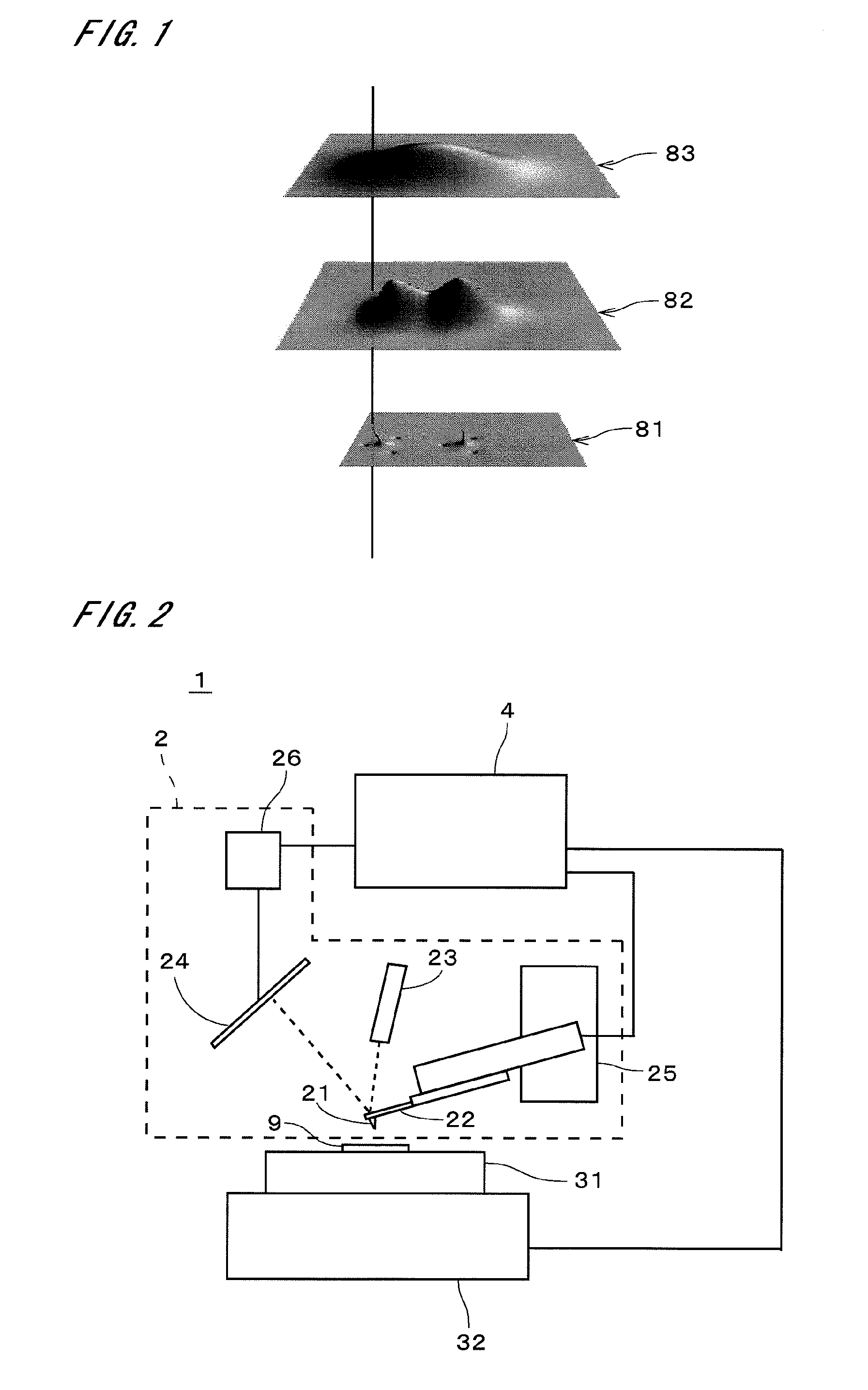
Above a sample (9) having magnetic domains, a distribution of magnetic force in a measurement plane (91) is obtained as a magnetic force image using a MFM, an auxiliary magnetic force image is obtained by performing measurement in a measurement plane (92) away from the measurement plane (91) by a distance d, and a difference between them is divided by the distance d to obtain a magnetic force gradient image. The magnetic force image and the auxiliary magnetic force image are Fourier transformed and substituted into a three-dimensional field obtaining equation derived from a general solution of the Laplace equation, and the three-dimensional field indicating the magnetic force is obtained. A state of the magnetic domains at the surface (93) of the sample (9) can be obtained with high accuracy by obtaining the three-dimensional field.

Description

TECHNICAL FIELD[0001]The present invention relates to a technique of obtaining a three-dimensional field of magnetic, electric, temperature and gravity potential and the like, a high-dimensional field extended by including time and the like, and a two-dimensional field by measurement.BACKGROUND ART[0002]Development of an apparatus which evaluates structure of magnetic domains on a magnetic material, is performed in parallel with density growth in magnetic recording to the magnetic material which is a recording medium. The scanning tunneling microscopy and the scanning electron microscopy using spin-polarized electrons are expected to have a resolution equal to or less than 5 nm. However, these apparatuses can only perform observation of the surface of magnetic material which is extremely clean, and it is not easy to apply them as practicable evaluation apparatuses or inspection apparatuses provided in a manufacturing line. Consequently, it is suggested to use the magnetic force micr...

Claims


Application Information

Patent Timeline
Patent Type & Authority Patents(United States)
IPC IPC(8): G01R33/02G01Q30/04G01Q60/50
CPCB82Y35/00G01Q30/04G01R33/10G01R33/0206G01R33/0385G01Q60/50B82Y25/00G01N27/90G01R29/12
Inventor KIMURA, KENJIROKOBAYASHI, KEIYAMADA, HIROFUMIMATSUSHIGE, KAZUMIHORIUCHI, TAKASHISATOH, NOBUONAKAI, AKIFUMI
Owner KYOTO UNIV
Learn More