Deflection plate for liquid jet printer

Active Publication Date: 2013-09-24
MILLIKEN & CO
View PDF14 Cites 2 Cited by
  • Summary
  • Abstract
  • Description
  • Claims
  • Application Information

AI Technical Summary

Benefits of technology

[0008]The dielectric preferably has a relatively high dielectric strength, thereby minimizing the thickness of the dielectric layer required to avoid breakdown of the electrical field. Additionally, the thinner the dielectric layer, the less likely that the deflecting plate will encroach upon the path of the liquid jet droplets, thereby decreasing the number of liquid droplets impinging upon the surface of the deflecting plate. By way of example, dielectrics having a dielectric strength of 4000 V / mil or greater, are believed to be particularly useful in the present invention. Dielectric layers ranging from 100 nm to 0.1 mm in thickness may be used.
[0009]The invention may further include a hydrophobic film overlaying the dielectric outer layer. Or, the dielectric layer may itself be hydrophobic. The hydrophobic film minimizes the size of the liquid droplets that coalesce on the deflecting plates. Smaller drops of liquid are less likely to cause arcing between the deflecting plates or other breakdown of the electrical field. Additionally, the hydrophobic film results in smaller drops of liquid releasing from the deflecting plates from gravity, and smaller drops of liquid are less noticeable, if they should drip from the deflecting plates on to the substrate.

Problems solved by technology

The accumulation can coalesce on the surface of the deflection plate reducing the effective gap to below the breakdown potential of air and cause arcing from one plate to the adjacent oppositely charged plate.

Method used


Image

  • Deflection plate for liquid jet printer
  • Deflection plate for liquid jet printer
  • Deflection plate for liquid jet printer

Examples


example 1

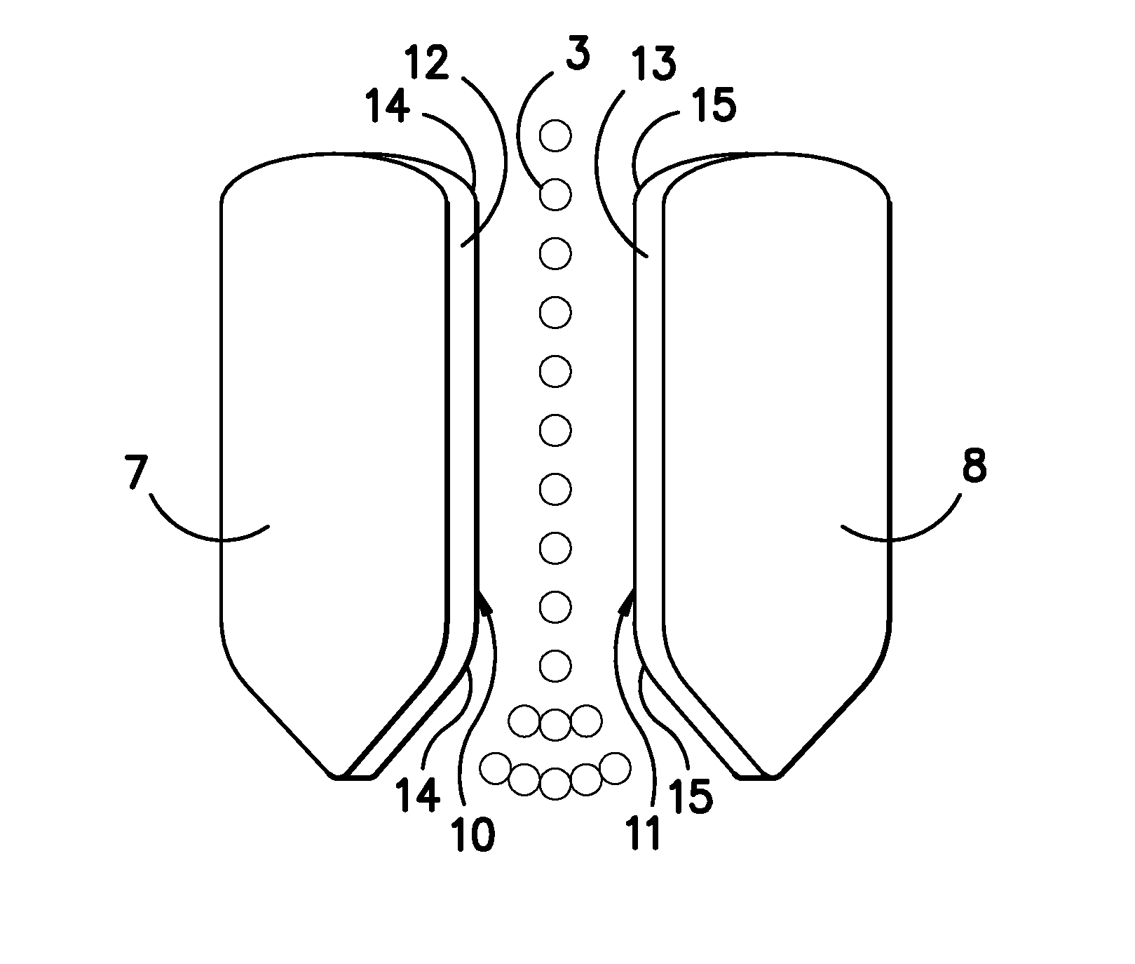
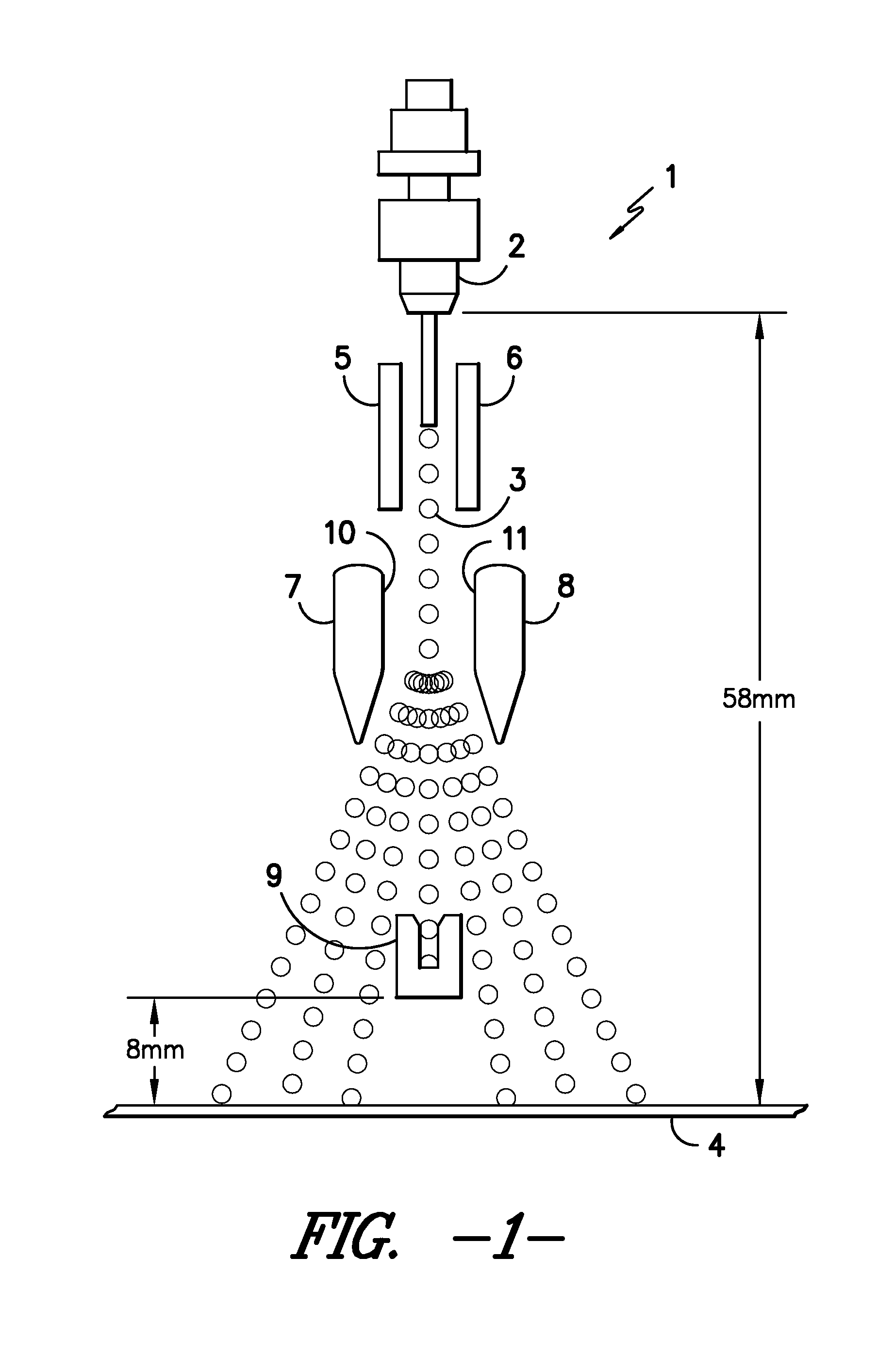
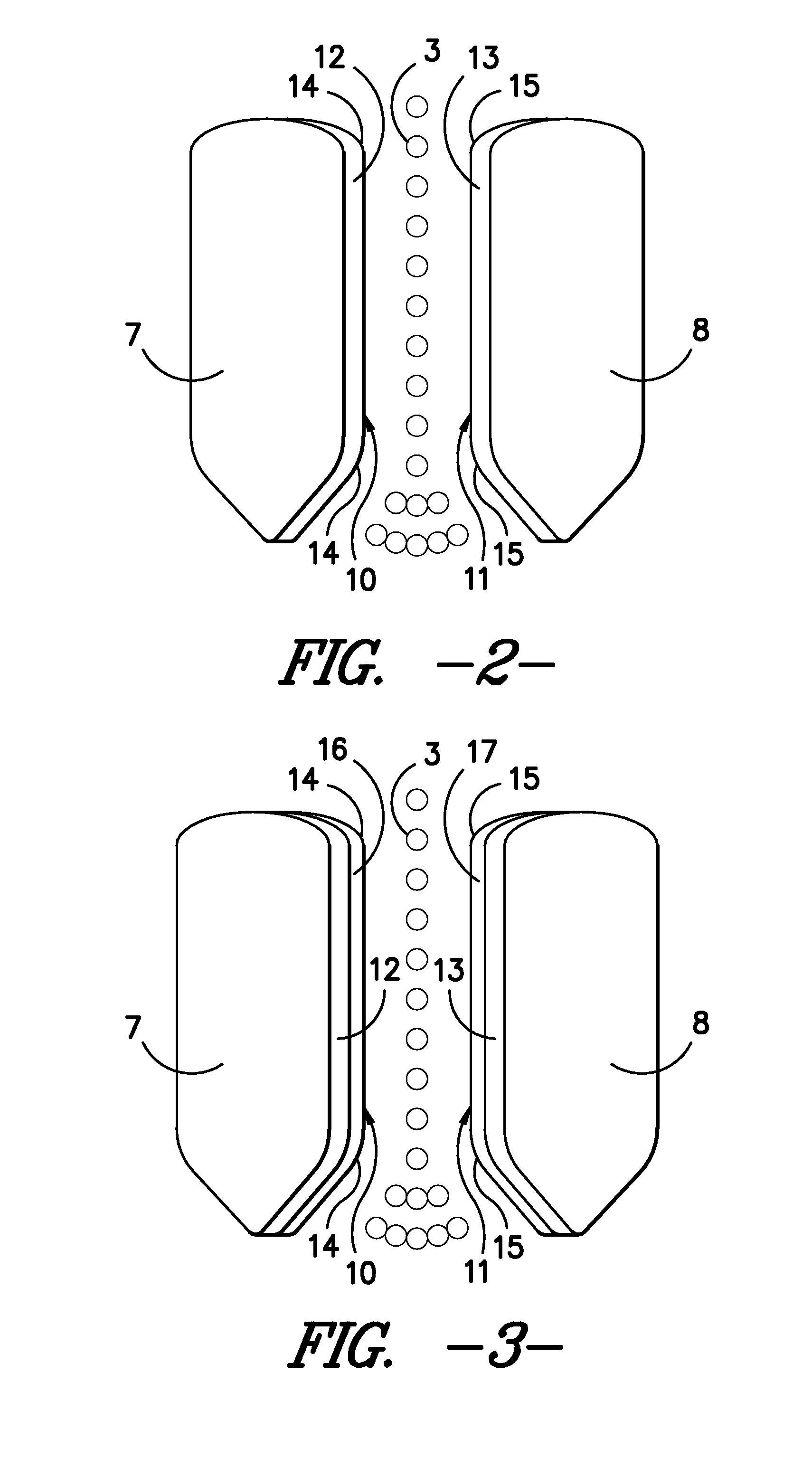
[0031]An aluminum deflecting plate was coated with Parylene C using vapor deposition, to create a dielectric layer. The dielectric layer was approximately 1.5 mils (40 μm) thick and had a dielectric strength of 5600 V / mil (measured using ASTM D 149 test method). The coated deflecting plates were used in a liquid jet printing apparatus, as shown in FIG. 1, with a spacing of 0.157 inches (4 mm) between the inside surfaces of the deflecting plates. The introduction of the dielectric coating greatly reduced arcing and droplet coalescence on the surface of the deflecting plate, without any negative impact on print quality observed.

example 2

[0032]A hydrophobic coating was prepared by homogenizing fumed silica particles (Aerosil R812S) in decane and blending 5 weight % of the silica with a fluoroalkyl acrylate copolymer (Unidyne TG658). The deflecting plates obtained from Example 1 were dip coated in the hydrophobic coating composition and cured at 250° F. for 5 minutes. The hydrophobic coating was found to reduce coalescence of liquid droplets and reduce the amount of liquid accumulated on the deflecting plates, when employed in a liquid jet printing apparatus, as shown in FIG. 1.

Applications

[0033]The present invention is useful in both continuous and on-demand liquid jet printers employing charged deflecting plates to direct the application of liquid droplet to a substrate. Useful substrates include paper, polymer film and textiles, including woven and knitted fabrics, carpet, rugs and carpet tile, and including textiles made of natural and synthetic fibers or combinations thereof. Of particular interest is the use of...


PUM


Abstract

A liquid jet printing apparatus is provided having a nozzle for emitting a stream of liquid droplets toward a substrate, a charging section for providing an electrical charge to liquid droplets and a pair of electrically conductive deflecting plates for deflecting the liquid droplets to a desired location on the substrate, wherein the inside face of the deflecting plates is provided with dielectric layer to minimize problems associated with liquid droplets collecting and coalescing on the deflecting plates.

Description

[0001]This invention relates generally to a liquid jet printer having electrically charged deflection plates to direct the path of a droplet of liquid, and in particular to deflection plates having a high dielectric strength coating on the surface to reduce arcing.BACKGROUND OF THE INVENTION[0002]The present invention is directed to a liquid jet printer having (i) a droplet formation section, such as a piezoelectric transducer, (ii) a droplet charging section, such as parallel metal plates, and (iii) a droplet deflection section, for directing the path of the droplet to the desired location on a substrate to be printed. In the case of continuous jet printing, a stream of individual droplets is produced, with some of the droplets impinging on the substrate in the desired pattern. The remaining droplets are intercepted by a collection device, such as a gutter, and are recycled to the droplet formation section, rather than printed on the substrate.[0003]U.S. Pat. No. 7,438,396 B2 discl...

Claims


Application Information

Patent Timeline
Patent Type & Authority Patents(United States)
IPC IPC(8): B41J2/085
CPCB41J2/07
Inventor LOVE, III, FRANKLIN S.LILLIE, JEFFREY J.MCBRIDE, DANIEL T.MONDAL, RAJIBMACMECCAN, ROBERT M.
Owner MILLIKEN & CO
Why Eureka
Try Eureka