Speed change gear and manufacturing method therefor

a technology of gear and manufacturing method, applied in the direction of gearing, oblique crank gearing, wobble plate gearing, etc., can solve the problems of increasing manufacturing cost, difficult to appropriately support the pin, and difficulty in assembling the gear, so as to achieve the effect of not impairing the assembling efficiency

Active Publication Date: 2013-09-24
JTEKT CORP
View PDF10 Cites 3 Cited by
  • Summary
  • Abstract
  • Description
  • Claims
  • Application Information

AI Technical Summary

Benefits of technology

[0013]The invention is made in the light of the above-described circumstances, and it is an object of the invention to provide a high-accuracy speed change gear without impairing assembling efficiency.
[0015]According to another feature of an example of the invention, one of an internal gear member and an eccentric member is coupled to one of an input shaft and an output shaft, the one side end portion of the pin is press-fitted in the insertion hole of one of the first rotating member and the second rotating member, and the one of the first rotating member and the second rotating member is coupled to the other one of the input shaft and the output shaft. That is, it is assumed that the first rotating member and the second rotating member are not fixed to a housing, or the like, but are coupled to the input shaft or the output shaft. Then, when the above configuration is employed, the other one of the input shaft and the output shaft is coupled to the rotating member having the insertion hole to which the one side end portion of the pin is press-fitted. Thus, the pin extracts only the axial rotation component from the oscillating rotation of the oscillating member, and the rotating member to which the pin is press-fitted and that supports the pin outputs or receives driving force. Therefore, it is possible to further reliably transmit driving force.
[0016]According to a further feature of an example of the invention, the pin has an intermediate portion between the one side end portion and the other side end portion, the outside diameter of the intermediate portion is equal to the outside diameter of one of the one side end portion and the other side end portion, and a step portion is formed at a portion at which the intermediate portion is coupled to the other one of the one side end portion and the other side end portion. The intermediate portion of the pin directly or indirectly contacts the cylindrical inner surface of the through-hole of the oscillating member to transmit driving force. Then, the intermediate portion of the pin having the step portion reliably contacts the inner peripheral surface of the through-hole, and the pin is supported at both ends by the insertion holes having the same diameter. Thus, the stability of the operation of the speed change gear may be improved. In addition, which one of the outside diameter of the one side end portion and the other side end portion should be set to be equal to the outside diameter of the intermediate portion is appropriately set on the basis of the structural relationship with other members. The outside diameter of the intermediate portion is set in consideration of, for example, a size required by a rolling bearing interposed between the intermediate portion and the inner peripheral surface of the through-hole, interference of the press-fitted one side end portion, and the like.
[0017]According to another feature of the invention, by way of example, the other side end portion of the pin is loosely fitted in one of the insertion hole of the first rotating member and the insertion hole of the second rotating member. It is known that, when a shaft member, such as the pin, is fitted in a hole, generally, there are three types of fit depending on the dimensional relationship, that is, interference fit by which interference is formed between the shaft member and the inner peripheral surface of the hole, loose fit by which a gap is formed between the shaft member and the inner peripheral surface of the hole and medium fit that is in between the interference fit and the loose fit. The interference fit is a state where the one side end portion of the pin is press-fitted in the corresponding insertion hole. Then, the other side end portion of the pin is inserted in the corresponding insertion hole with a gap between the pin and the inner peripheral surface of the insertion hole so as to achieve a loose fit. Thus, for example, when the rotating member is assembled to the inside of the internal gear member at the last stage of the work for assembling the speed change gear, it is possible to allow the protruding pin to be easily inserted into the insertion hole. In this way, the pin may be reliably supported at both ends without impairing the efficiency of assembling the speed change gear.

Problems solved by technology

Thus, it may be difficult to appropriately support the pins in a state where the speed reduction gear is driven.
However, because both end portions of each pin are press-fitted to the output member and the support member, work for assembling the gear may be difficult.
In addition, if the dimensional accuracy required for each member increases, manufacturing cost also increases.
However, because each coupling member is not in contact with the inner peripheral surface of a corresponding one of the through-holes formed in the planet gear, the coupling members do not contribute to transmission of power.
Even if the coupling member is brought into contact with the inner peripheral surface of a corresponding one of the through-holes of the planet gear to thereby transmit power, there is the same problem as that of the speed reduction gear in the related art described in JP-A-7-248046 because both end portions of are press-fitted.
That is, even if the adjustment pins are assumed to contribute to transmission of power, a backlash of the output shaft in the circumferential direction is presumed to occur because both end portions of each adjustment pin are not press-fitted to the output member or the support member.
As described above, in the speed change gear in which pins that transmit power are supported at both ends, there is a possibility that a backlash in the circumferential direction may occur or assembling work may become difficult due to various configurations for supporting each end portion of the pin.

Method used


Image

  • Speed change gear and manufacturing method therefor
  • Speed change gear and manufacturing method therefor
  • Speed change gear and manufacturing method therefor

Examples


Embodiment Construction

[0026]Hereinafter, embodiments of the invention will be described with reference to the accompanying drawings.

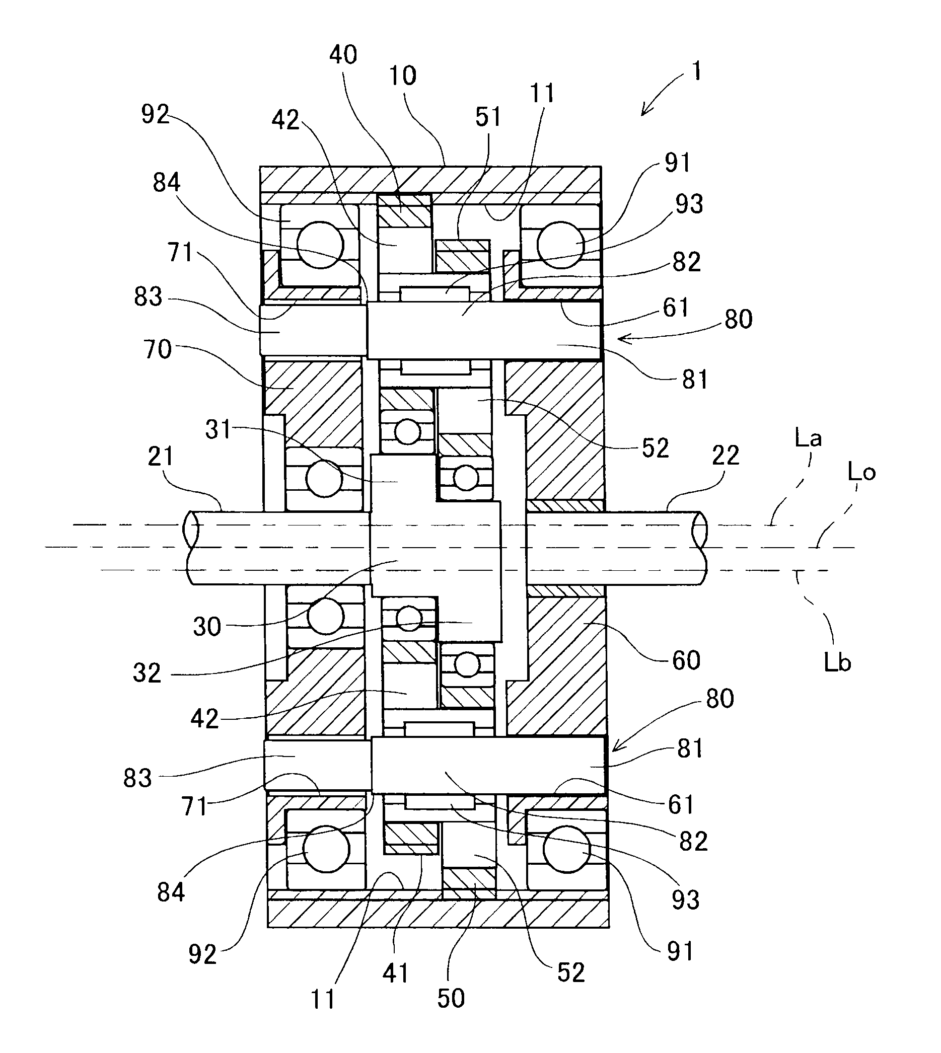
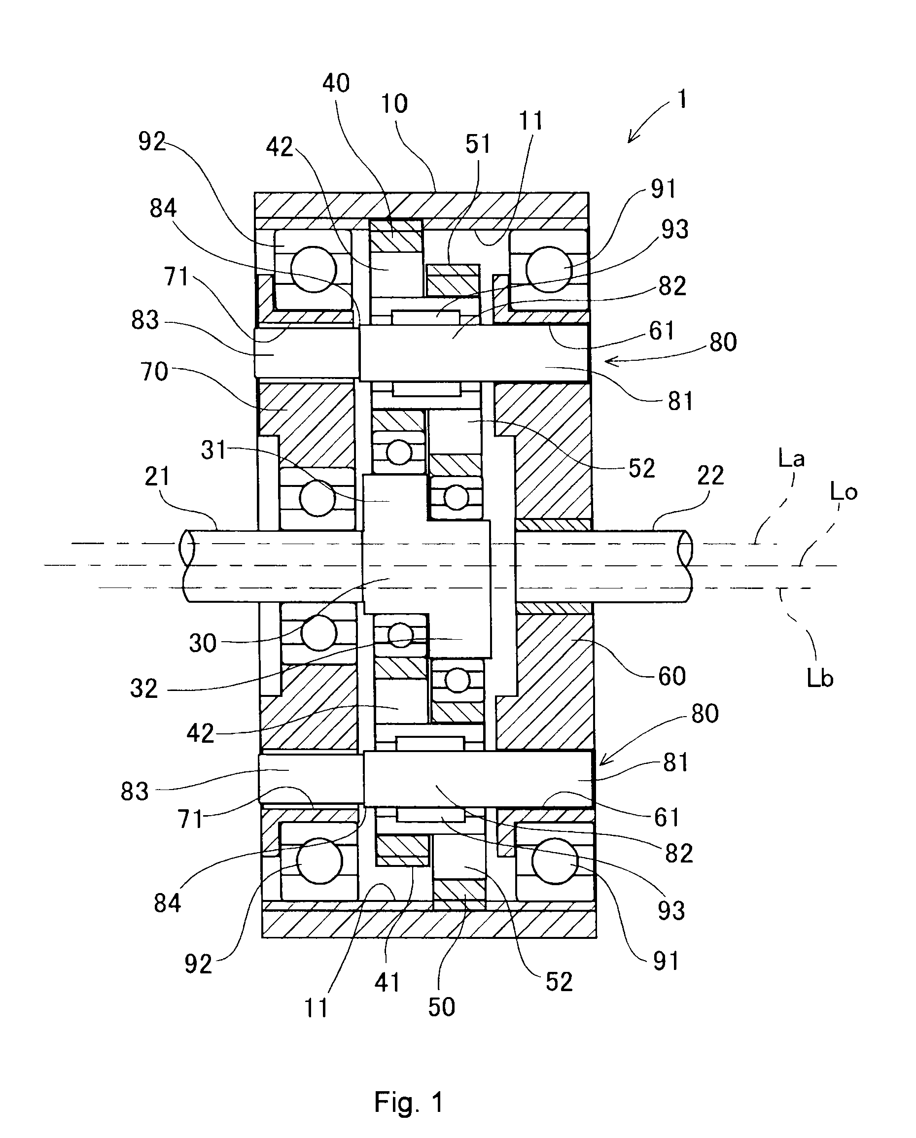
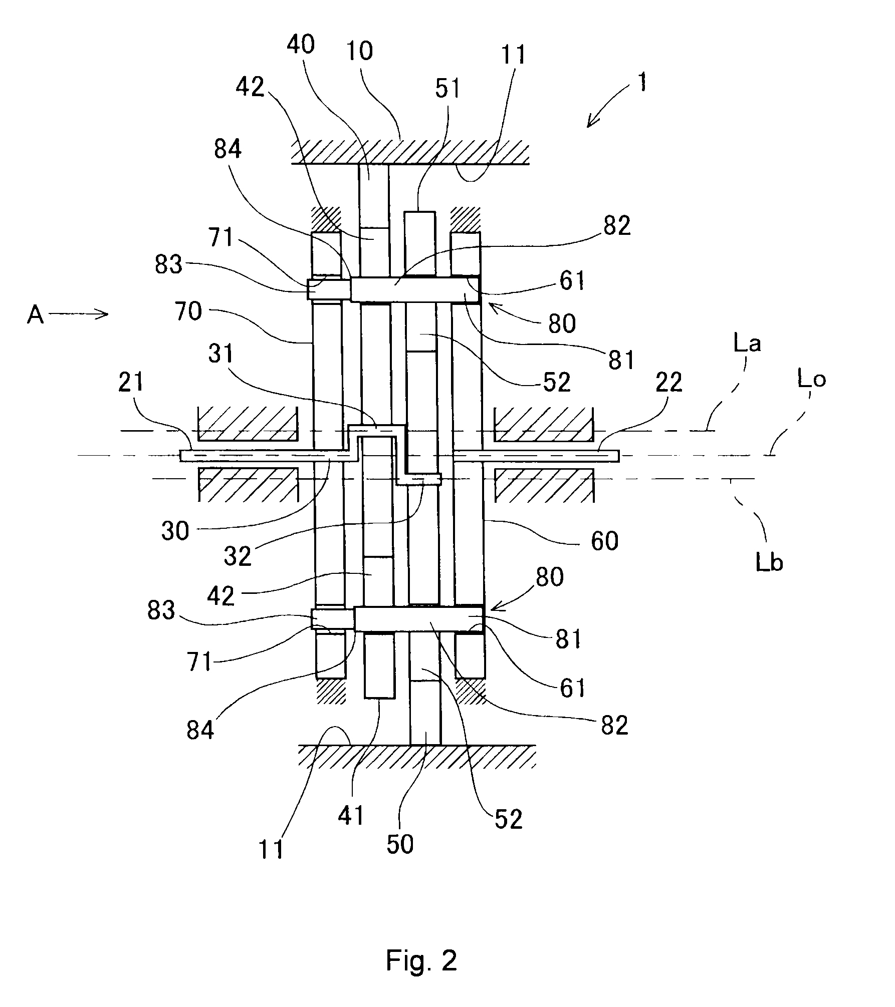
[0027]Hereinafter, a speed change gear according to an embodiment of the invention will be described with reference to the accompanying drawings. A speed reduction gear 1 to which the speed change gear according to the invention is applied will be described with reference to FIG. 1 to FIG. 5. FIG. 1 is a sectional view that shows the configuration of the speed reduction gear 1. FIG. 2 is a conceptual view that shows the basic configuration of the speed reduction gear 1. FIG. 3 is a view when viewed in the direction of the arrow A in FIG. 2 through a support plate 70. FIG. 4 is a side view that shows a pin 80 in the speed reduction gear 1. FIG. 5 is a side view that shows an output plate 60 and the support plate 70 in the speed reduction gear 1.

[0028]The speed reduction gear 1 is formed mainly of a housing 10, an input shaft member 21, an output shaft member 22, a crankshaft ...


PUM

PropertyMeasurementUnit
diameteraaaaaaaaaa
speedaaaaaaaaaa
timeaaaaaaaaaa

Abstract

A speed change gear includes: an internal gear member; an eccentric member; an oscillating member; a pair of first and second rotating members; and a pin that is supported at both ends by insertion holes of the first and second rotating members. The insertion hole and the insertion hole have the same diameter. The outside diameter of the other side end portion of the pin is smaller than the outside diameter of one side end portion of the pin such that the one side end portion is press-fitted in the corresponding insertion hole and the other side end portion is supported by the corresponding insertion hole.

Description

INCORPORATION BY REFERENCE / RELATED APPLICATION[0001]This application claims priority to Japanese Patent Application No. 2010-078671 filed on Mar. 30, 2010 the disclosure of which, including the specification, drawings and abstract, is incorporated herein by reference in its entirety.BACKGROUND OF THE INVENTION[0002]1. Field of the Invention[0003]The invention relates to a speed change gear.[0004]2. Discussion of Background[0005]A speed change gear is used as a speed reduction gear or a speed increasing gear that changes the speed of rotation input from a motor, or the like. As such a speed change gear, there is a known speed reduction gear that uses a planet gear mechanism in order to obtain a high change gear ratio. For example, a speed reduction gear described in Japanese Patent Application Publication No. 2002-266955 (JP-A-2002-266955) and Japanese Patent Application Publication No. 7-248046 (JP-A-7-248046) oscillatingly rotates a planet gear with the rotation of an input shaft a...

Claims


Application Information

Patent Timeline
Patent Type & Authority Patents(United States)
IPC IPC(8): F16H23/00
CPCF16H1/32F16H2001/324F16H2001/325Y10T29/49467
Inventor WAKIDA, MAYUKOYAMAMORI, MOTOYASUANDO, ATSUSHIHATTORI, KAZUYAOTA, HIROMICHIKATO, YOSHINOBUNAGUMO, KOJIHONDA, TOMOHIRO
Owner JTEKT CORP
Why Eureka
Try Eureka