
MEMS microgenerator cell and microgenerator cell array

a technology of microgenerator cells and microgenerators, which is applied in the direction of generators/motors, nuclear engineering, electric fuzes, etc., can solve the problem of plasma out of the chamber

Inactive Publication Date: 2013-09-24
UNIV OF SOUTH FLORIDA
View PDF7 Cites 2 Cited by
  • Summary
  • Abstract
  • Description
  • Claims
  • Application Information

AI Technical Summary

Benefits of technology

The present invention provides a microgenerator cell and array that has many benefits. It eliminates the need for moving parts, valves, and external tanks. The microgenerator is the same size as the MEMS sensors and actuators that it powers. Additionally, it is environmentally friendly and efficient.

Problems solved by technology

The rupture of the diaphragm results in the flow of plasma out of the chamber.

Method used


Image

  • MEMS microgenerator cell and microgenerator cell array
  • MEMS microgenerator cell and microgenerator cell array
  • MEMS microgenerator cell and microgenerator cell array

Examples


Embodiment Construction

[0019]In the following detailed description of the preferred embodiments, reference is made to the accompanying drawings, which form a part hereof, and within which are shown by way of illustration specific embodiments by which the invention may be practiced. It is to be understood that other embodiments may be utilized and structural changes may be made without departing from the scope of the invention.

[0020]MEMS structures known in the art today are designed to use macroscopic power supplies, thereby placing limits on the functionality of MEMS structures in many applications. A significant consideration for micro power generators is that the system exhibits high power density, compactness, and superior conversion efficiencies. A system meeting these objectives is of ultimate importance in power application for MEMS systems.

[0021]When a conducting fluid is under the influence of an electromagnetic field, the flow pattern is altered. The magnetic field and the motion of conducting f...


PUM


Abstract

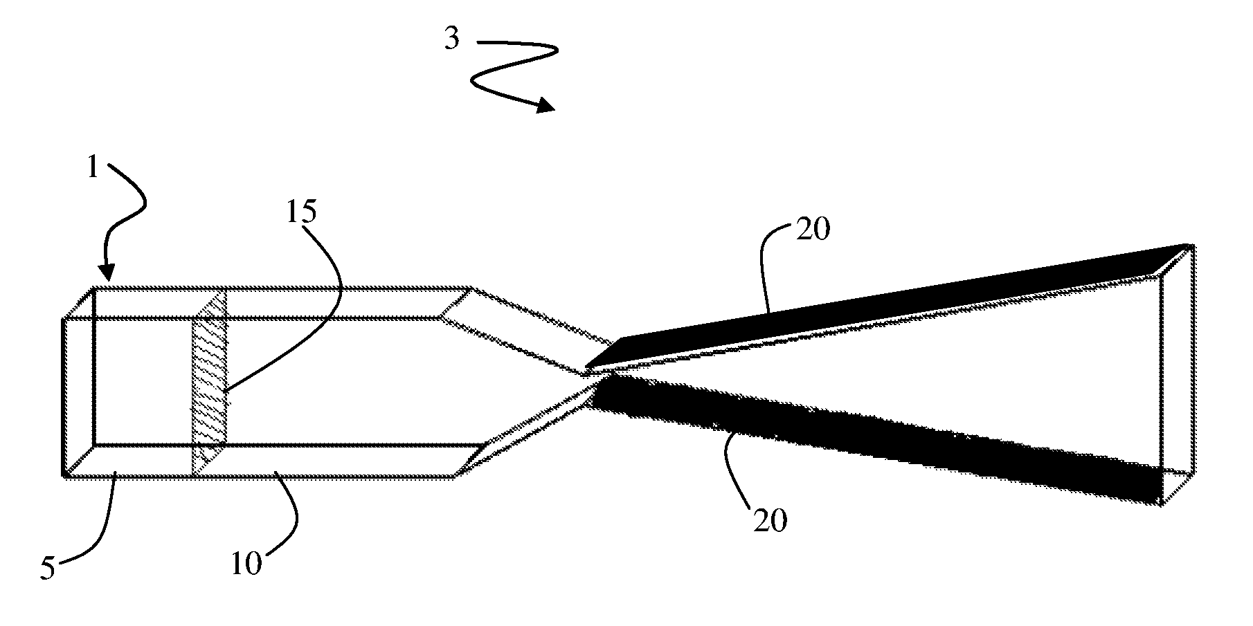
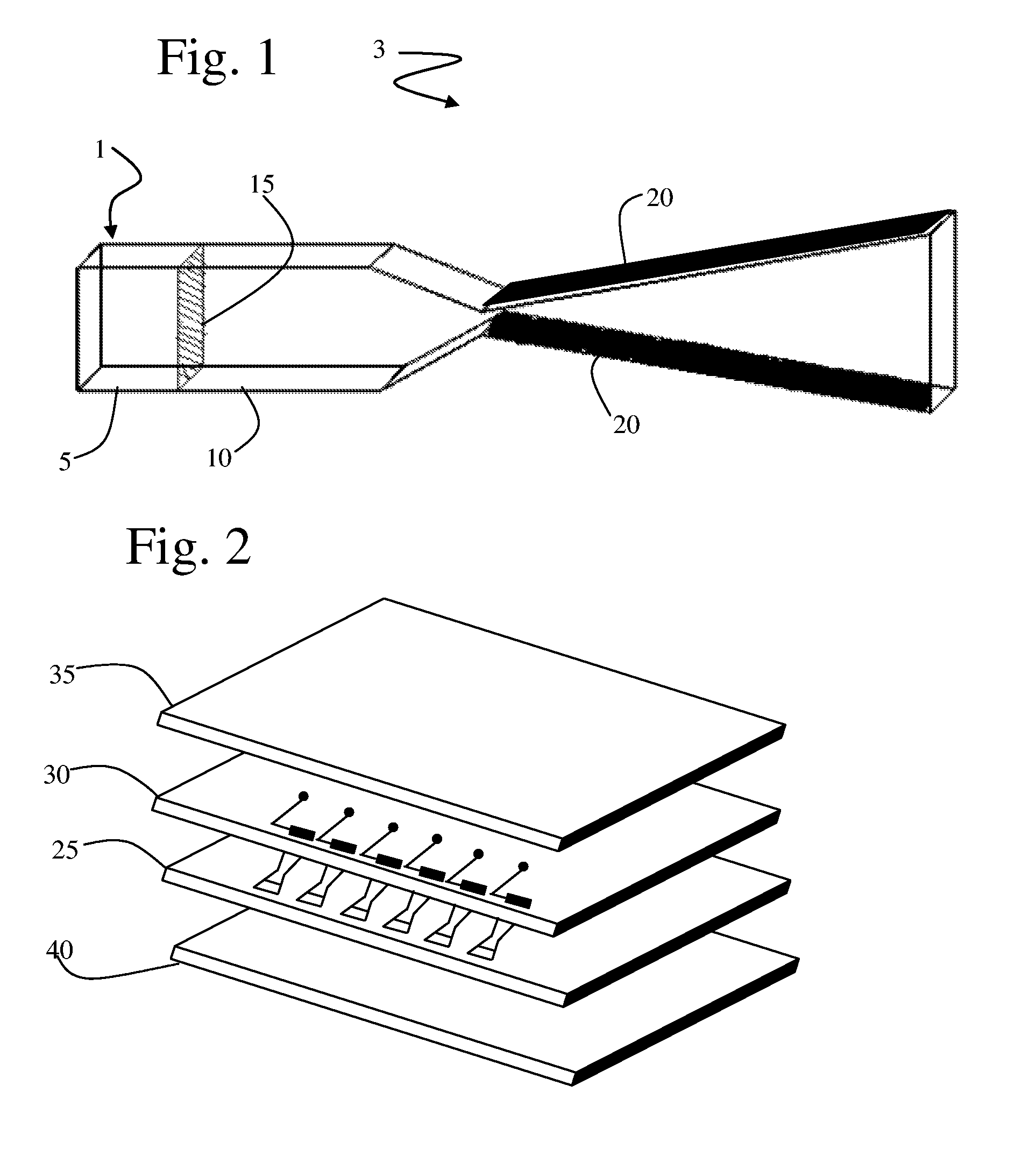
A microelectrical mechanical system (MEMS) microgenerator cell and array is disclosed. The MEMS microgenerator cell of the present invention is effective in the conversion of thermal energy to electrical energy. In accordance with the present invention, an explosive material is loaded into a chamber. A diaphragm seals the chamber, containing a plasma material. The explosive material is subsequently heated to its ignition temperature thereby raising the pressure in the chamber until the diaphragm ruptures. The rupture of the diaphragm results in the flow of plasma out of the chamber. Upon exiting the chamber, the plasma is forced to flow between two parallel rectangular electrodes. A magnetic field is applied in a direction orthogonal to both the plasma flow and the electrodes, thereby generating an electromagnetic field sufficient to a power source for MEMS devices.

Description

CROSS-REFERENCE TO RELATED APPLICATIONS[0001]This application is a continuation of International Patent Application No. PCT / US2004 / 008625, filed on Mar. 22, 2004, which claims the benefit of U.S. Provisional Patent Application Ser. No. 60 / 320,026 filed Mar. 20, 2003.BACKGROUND OF INVENTION[0002]MEMS devices are based on using microelectronic wafer fabrication techniques to produce complex shapes in the μm to mm size range with embedded sensors, actuators and circuitry. Microelectromechanical systems (MEMS) have been developed as alternatives to conventional electromechanical devices. MEMS devices are potentially low-cost devices, due to the use of microelectronic fabrication techniques. New functionality also may be provided, because MEMS devices can be much smaller than conventional electromechanical devices.[0003]Micro power generation techniques known in the art include thermo-electric converters, micro combustion engines, micro fuel cells, and micro fuel reformers. Hydrocarbon f...

Claims


Application Information

Patent Timeline
Patent Type & Authority Patents(United States)
IPC IPC(8): H02K44/00H02K44/08H02N3/00
CPCH02K44/08H02N3/00
Inventor BHANSALI, SHEKHARPOPURI, RAJSEKHAR
Owner UNIV OF SOUTH FLORIDA
Learn More