Eureka AIR delivers breakthrough ideas for toughest innovation challenges, trusted by R&D personnel around the world.

Aircraft system and method for selecting aircraft gliding airspeed during loss of engine power

a technology of aircraft gliding and engine power, which is applied in the direction of emergency apparatus, process and machine control, and navigation instruments, etc., can solve the problems of limiting the glide area where the pilot can fly, reducing the distance the airplane may reach, and determining the optimal gliding speed for maximizing gliding distance, etc., to achieve optimal gliding speed, maximize gliding distance, and maximize the effect of aircraft gliding distan

Active Publication Date: 2013-09-24
HONEYWELL INT INC
View PDF16 Cites 21 Cited by
  • Summary
  • Abstract
  • Description
  • Claims
  • Application Information

AI Technical Summary

Benefits of technology

The patent describes a method for determining the best speed for an aircraft that has lost its engines and is gliding. It involves figuring out the speed of the air, the wind speed, and if the engines are still working or not. Then, based on these factors, the method calculates the best speed for the aircraft to maximize the distance it can glide. This information is then given to the pilot of the aircraft. The technical effect of the patent is to provide a way for pilots to safely and efficiently manage an aircraft that has lost its engines and is gliding.

Problems solved by technology

With so many tasks to perform at once, it is difficult to determine and maintain the proper gliding speed for maximizing gliding distance.
If the pilot has not enough experience with gliding, the incorrect setting of the gliding speed may significantly reduce a distance which the airplane may reach.
This limits the glide area where the pilot can select a field for emergency landing.

Method used


Image

  • Aircraft system and method for selecting aircraft gliding airspeed during loss of engine power
  • Aircraft system and method for selecting aircraft gliding airspeed during loss of engine power
  • Aircraft system and method for selecting aircraft gliding airspeed during loss of engine power

Examples


Embodiment Construction

[0019]The following detailed description is merely illustrative in nature and is not intended to limit the embodiments of the subject matter or the application and uses of such embodiments. Any implementation described herein as exemplary is not necessarily to be construed as preferred or advantageous over other implementations. Furthermore, there is no intention to be bound by any expressed or implied theory presented in the preceding technical field, background, brief summary, or the following detailed description.

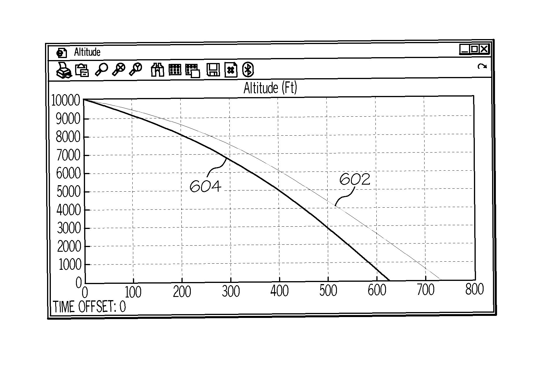
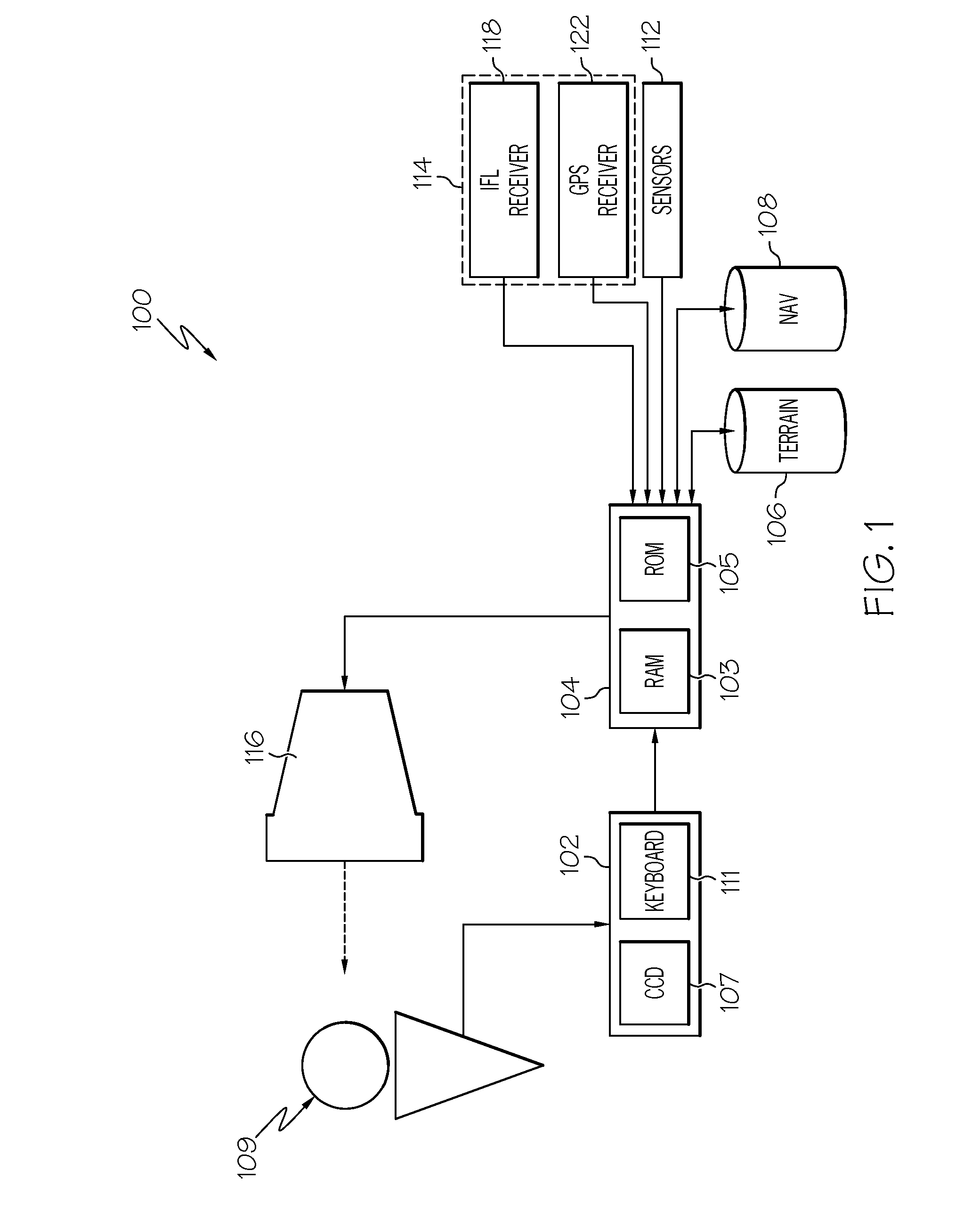
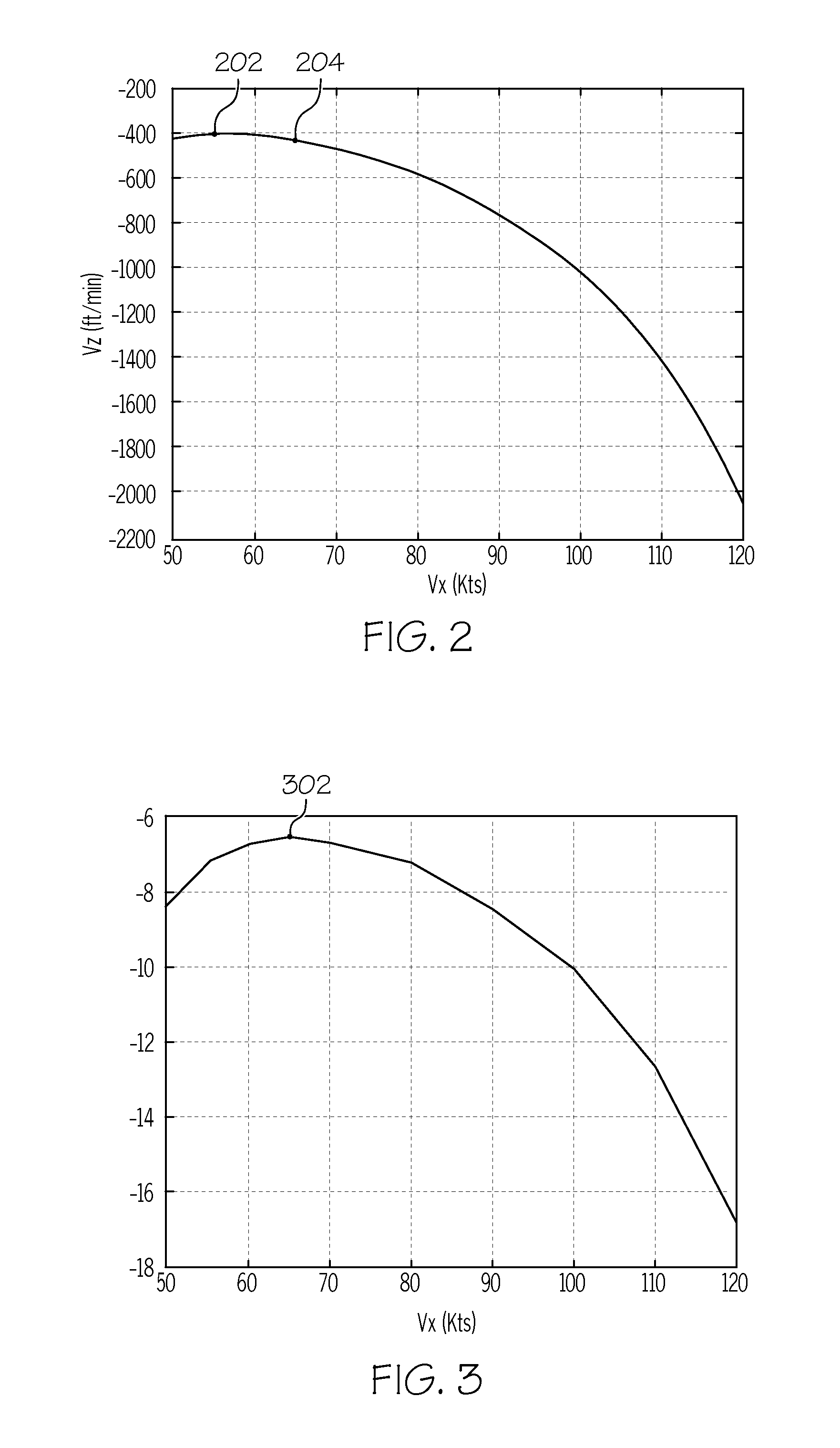
[0020]A system and method are provided for automatically calculating gliding speed of an aircraft for maximizing gliding distance upon engine failure (loss of all power or thrust). The calculation is performed using the aircraft polar curve of vertical descent versus horizontal travel for the particular aircraft. Data considered for constructing the polar curve include head wind, vertical wind, true airspeed, and optionally the center of gravity (CG) and weight of the ai...


PUM


Abstract

A method and aircraft system are provided for determining an optimal gliding speed that maximizes gliding distance of the aircraft upon engine failure, and comprises calculating the optimal gliding speed from a speed polar curve, true airspeed, heading, and vertical wind speed. The polar curve may be constructed with consideration of the aircraft center of gravity and weight. The calculated gliding speed, which may be restricted to a threshold, is provided to the pilot and optionally to an autopilot. The method is repeated periodically, or if the wind vertical or horizontal velocities exceed a threshold for a predetermined period of time.

Description

TECHNICAL FIELD[0001]The exemplary embodiments described herein generally relate to determining optimal aircraft gliding speed during loss of engine power and more particularly to maximizing aircraft gliding distance for reaching an emergency landing area while experiencing loss of engine power.BACKGROUND[0002]Under normal operating conditions, an aircraft flies from one airport to another with the pilot controlling power, airspeed, and vertical climb or descent rates, typically for minimizing fuel consumption and / or time en route. With complete or partial engine failure (loss of all or substantially all engine power), a relatively quick determination must be made of gliding speed, rate of descent, and aircraft configuration to maximize the gliding distance for reaching an emergency landing area or airport. With loss of engine power, there are many other tasks to be performed by the pilot, including contacting air traffic control, monitoring other traffic, determining the reason for...

Claims


Application Information

Patent Timeline
Patent Type & Authority Patents(United States)
IPC IPC(8): G05D1/00
CPCG05D1/105G05D1/106
Inventor TOMAS, JAN
Owner HONEYWELL INT INC
Why Eureka
Eureka Blog
Learn More