Enclosure for outside plant equipment with interconnect for mating printed circuit boards, printed circuit board device and method of repairing outside plant equipment

a technology of printed circuit boards and enclosures, applied in the direction of coupling device connections, electrical apparatus casings/cabinets/drawers, instruments, etc., can solve the problems of thermal interface materials that are a function of the cost of thermal interface materials is a function of both thermal conductivity and hardness, and the cost of thermal interface materials is typically more expensive than lower conductivity materials

Active Publication Date: 2013-10-01
ADTRAN
View PDF64 Cites 20 Cited by
  • Summary
  • Abstract
  • Description
  • Claims
  • Application Information

AI Technical Summary

Problems solved by technology

This type of construction has several drawbacks, especially when used with an OSP Digital Subscriber Line Access Multiplexer (DSLAM) enclosure.
If the heat sink is removed from the component on the PCB for troubleshooting, there is a possibility of damage to the integrated circuit mounted to the PCB from overheating, because of lack of a heat sink.
Also, some surface mount components do not sit flush on the PCB, due to component float during the solder reflow process.
Also, the cost of the thermal interface material is a function of both thermal conductivity and hardness, as well as, sheer volume of the material used.
The higher thermal conductivity material is typically more expensive than lower conductivity material.
The softer material is typically more expensive than the harder material.
Additionally, it is difficult to generate accurate thermal images of components when the heat sink is mounted to the component side of the PCB, and thus, positioned over the component.
There is also an issue with such construction because it is difficult to interconnect PCB's together.
The heat sink covers the components on the component side, making interconnection difficult.
Thus, an issue arises of how to connect multiple PCB's together in an outside plant equipment enclosure.

Method used


Image

  • Enclosure for outside plant equipment with interconnect for mating printed circuit boards, printed circuit board device and method of repairing outside plant equipment
  • Enclosure for outside plant equipment with interconnect for mating printed circuit boards, printed circuit board device and method of repairing outside plant equipment
  • Enclosure for outside plant equipment with interconnect for mating printed circuit boards, printed circuit board device and method of repairing outside plant equipment

Examples


Embodiment Construction

[0027]The present invention will now be described more fully hereinafter with reference to the accompanying drawings, in which preferred embodiments of the invention are shown. This invention may, however, be embodied in many different forms and should not be construed as limited to the embodiments set forth herein. Rather, these embodiments are provided so that this disclosure will be thorough and complete, and will fully convey the scope of the invention to those skilled in the art. Like numbers refer to like elements throughout.

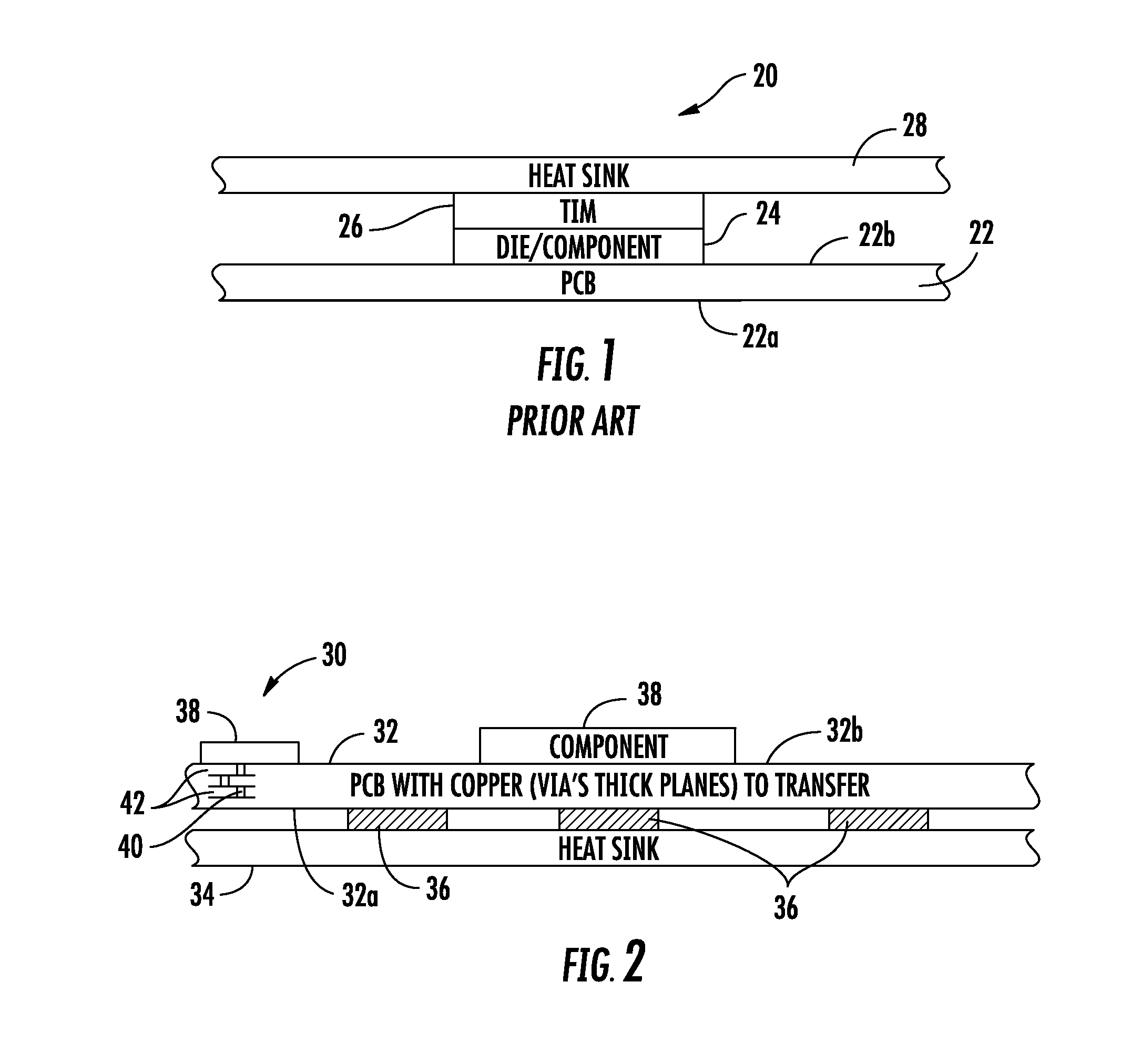
[0028]FIG. 1 is a prior art example of a heat sink device 20 showing a Printed Circuit Board (PCB) 22 having a circuit side 22a and component side 22b. A semiconductor die or other electronic component 24 is mounted on the component side opposite the circuit side. This is a typical configuration and includes a Thermal Interface Material (TIM) 26 connected on top of the electronic component 24 and a heat sink 28, such as a heat sink plate, secured to the TI...


PUM


Abstract

An enclosure for outside plant equipment includes a base unit and first Printed Circuit Board (PCB) carried by the base unit and having a circuit side and opposing component side on which electronic components are mounted. A heat sink is connected to the first PCB at the circuit side and configured to dissipate heat from any electronic components mounted on the first PCB at the component side. A cover is attached to the base unit and has an inside surface covering the enclosure. A second PCB has a circuit side and opposing component side on which electronic components are mounted. The second PCB is supported by the inside surface of the cover. A heat sink is connected to the second circuit board at the circuit side and configured to dissipate heat from any electronic components mounted on the second PCB. A PCB finger connector interconnects the first and second PCB's at the component side.

Description

FIELD OF THE INVENTION[0001]This invention relates to enclosures for outside plant equipment, heat sinks used with printed circuit boards for such outside plant equipment, and method of repairing same.BACKGROUND OF THE INVENTION[0002]Electronics are typically cooled from the top of the component with an interface, for example, a Thermal Interface Material (TIM) located between the top of the component that is secured on a Printed Circuit Board (PCB) and a heat sink, such as a conventional heat sink plate. This type of structure is used in many conventional devices, including many telecommunications Outside Plant (OSP) Equipment enclosures. This type of construction has several drawbacks, especially when used with an OSP Digital Subscriber Line Access Multiplexer (DSLAM) enclosure. If the unit requires testing or trouble-shooting, the PCB must be removed from the enclosure forming the heat sink in order to access electronic components. If the heat sink is removed from the component o...

Claims


Application Information

Patent Timeline
Patent Type & Authority Patents(United States)
IPC IPC(8): H05K7/20
CPCH05K7/20445
Inventor MCCLEARY, JACOB D.
Owner ADTRAN
Why Eureka
Try Eureka