
Method for transmitting/receiving data in a multiple-input multiple-output system using multi-carrier

a data transmission and multi-output technology, applied in the field of multi-input multiple output (mimo) systems, can solve the problems of increasing system complexity and costs, unavoidably increasing the complexity and inability to expect the high data transmission date, so as to achieve effective communication, increase communication efficiency, and facilitate the design of the transmission/reception end

Inactive Publication Date: 2013-10-01
LG ELECTRONICS INC
View PDF4 Cites 21 Cited by
  • Summary
  • Abstract
  • Description
  • Claims
  • Application Information

AI Technical Summary

Benefits of technology

This patent text describes a new way to improve wireless communications. It solves problems of previous methods by using a phase-shift-based precoding scheme. This allows for easier design and increased efficiency in establishing communications. The invention can also convert a flat-fading channel to a frequency-selective channel for better communication. Additionally, a Hermitian matrix or rotation matrix can be applied to further reduce complexity and increase decoding gain. Overall, this patent presents a more effective way to optimize wireless communication.

Problems solved by technology

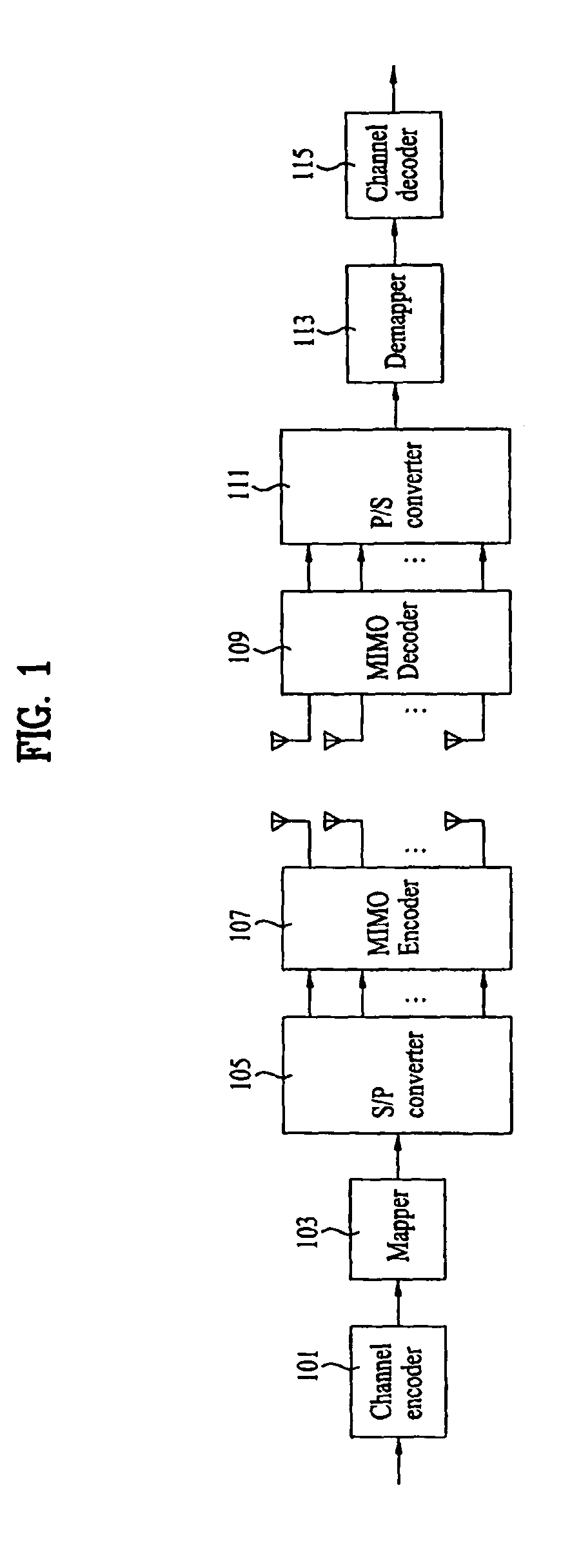
The above-mentioned MIMO schemes have different performances according to a variety of factors, i.e., a UE (User Equipment) speed, a channel situation, and the number of multi-antennas, such that schemes of different structures must be applied according to channel conditions, resulting in an increase of system complexity and costs.
As a result, the space-time code has a disadvantage in that it unavoidably increases the complexity of the transmission / reception end.
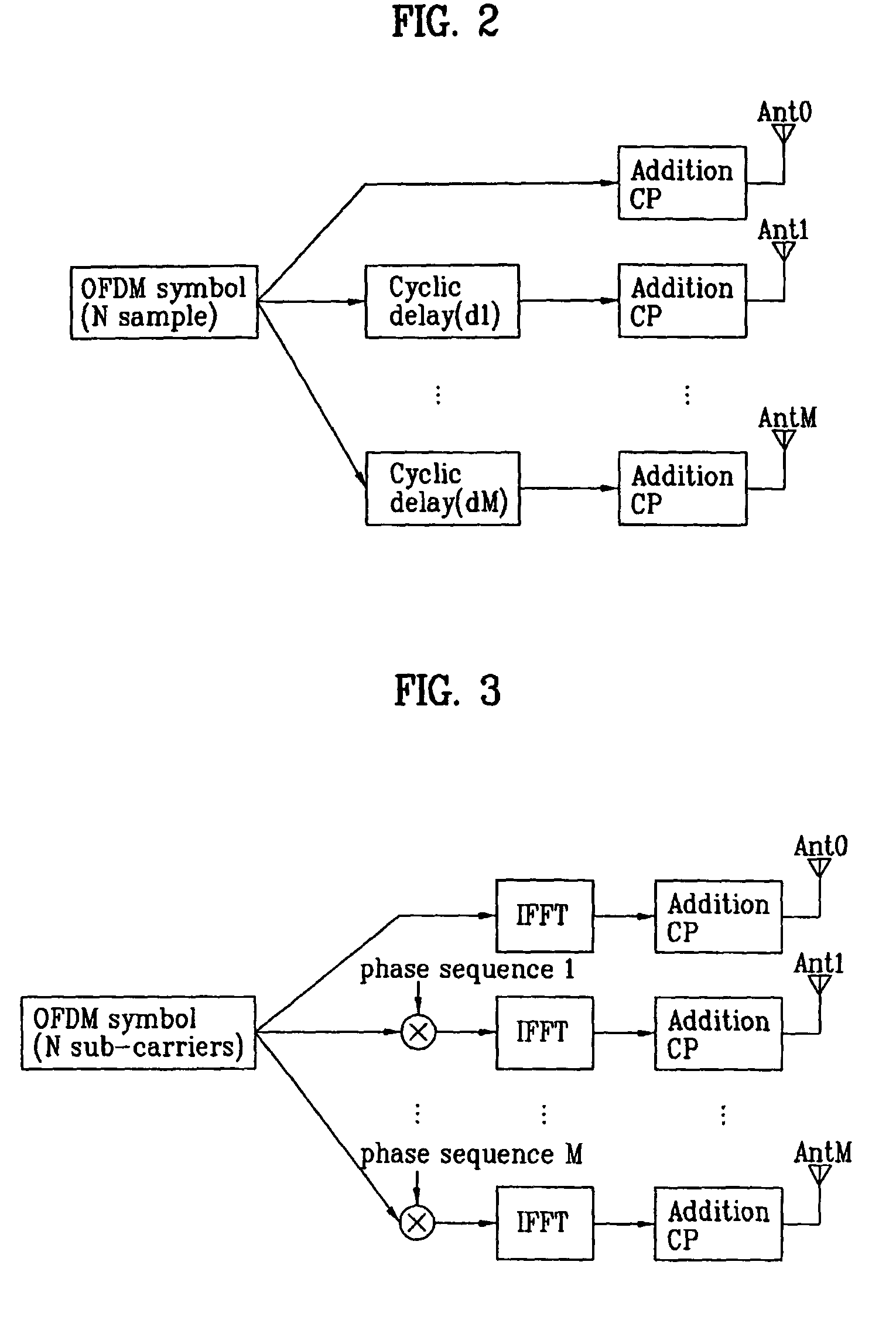
The CDD scheme has a spatial multiplexing rate of 1, such that it is unable to expect the high data transfer date.
If resources are fixedly allocated, the CDD scheme has difficulty in acquiring the above gain.
Therefore, the codebook-based precoding scheme is improper for a mobile environment of an abrupt channel variation.
Also, when the conventional codebook-based precoding scheme is used, the required memory capacity increases and the system complexity increases because each of the transmission / reception ends needs to have a codebook, and because different codebooks are required according to the number of Tx antennas and the special multiplexing rate.

Method used


Image

  • Method for transmitting/receiving data in a multiple-input multiple-output system using multi-carrier
  • Method for transmitting/receiving data in a multiple-input multiple-output system using multi-carrier
  • Method for transmitting/receiving data in a multiple-input multiple-output system using multi-carrier

Examples


embodiment 1

Phase-Shift-Based Precoding Matrix

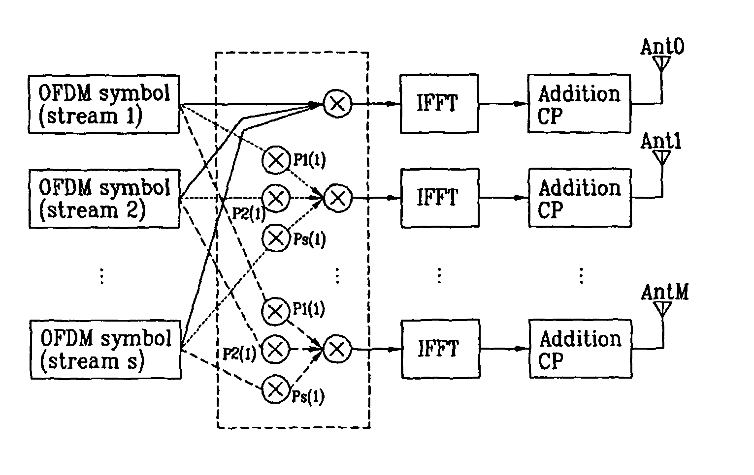
[0059]FIG. 5 is a block diagram illustrating the principal components of a transmission / reception end of the phase-shift-based precoding according to the present invention.

[0060]Referring to FIG. 5, the phase-shift-based precoding method transmits all streams to be transmitted via all antennas, multiplies the Tx streams by sequences of different phases, and transmits the multiplied result. Generally, if a phase sequence generated by a small cyclic delay value is used, the frequency selectivity in a channel occurs in the receiver, and the channel capacity increases or decreases according to frequency bands. In other words, the transmitter can select a specific part having good channel quality among frequency bands fluctuating by a relatively small cyclic delay value, and than allocate the selected part to a user equipment (UE) to get scheduling gain.

[0061]In this case, the present invention may use the phase-shift-based precoding matrix to apply a cy...

embodiment 2

Phase-Shift-Based Precoding Matrix According to Generalized Phase Shift Diversity Scheme

[0072]If the number of antennas is Nt (where Nt is a natural number of at least 2) and the spatial multiplexing rate is R, the phase-shift-based precoding matrix can be represented by the following equation 5. The phase-shift-based precoding matrix of Equation 5 is represented by the generalized format of the conventional phase shift diversity scheme. The MIMO scheme of Equation 5 may also be referred to as a generalized phase shift diversity (GPSD) scheme.

[0073]PNt×Rk=⁢(⁢w1,1kw1,2k…w1,Rkw2,1kw2,2k…w2,Rk⋮⋮⋱⋮wNt,1kwNt,2k…wNt,Rk⁢)=⁢(⁢ⅇjθ1⁢k0…00ⅇjθ2⁢k…0⋮⋮⋱⋮00…ⅇjθNt⁢k⁢)⁢(UNt×Rk)[Equation⁢⁢5]

[0074]As can be seen from Equation 5, the phase-shift-based precoding matrix is implemented by the product of a phase shift diagonal matrix including the resource index k and a unitary matrix.

[0075]In this case, PNt×Rk is indicative of a phase-shift-based precoding matrix of the k-th sub-carrier of the MIMO-OFDM s...

embodiment 3

Extended-Diagonal Matrix Addition of Phase-Shift-Based Precoding Matrix

[0090]If Equation 5 or 7 is extended, the phase-shift-based precoding matrix of the following equation 10 can be constructed.

[0091]PNt×Rk=⁢(w1,1kw1,2k…w1,Rkw2,1kw2,2k…w2,Rk⋮⋮⋱⋮wNt,1kwNt,2k…wNt,Rk⁢)=⁢D1⁡(UNt×Rk)⁢D2=⁢(ⅇj⁢⁢θ1⁢k0…00ⅇj⁢⁢θ2⁢k…0⋮⋮⋱⋮00…ⅇj⁢⁢θNt⁢k)⁢(UNt×Rk)⁢(ⅇj⁢⁢θ′1⁢k0…00ⅇj⁢⁢θ′2⁢k…0⋮⋮⋱⋮00…ⅇj⁢⁢θ′R⁢k)[Equation⁢⁢10]

[0092]Compared with Equation 5, Equation 10 includes a first diagonal matrix D1 and a second diagonal matrix D2. In this case, each row and each column of the phase-shift-based precoding matrix have independent phases, resulting in the implementation of a variety of frequency diversity gains.

[0093]FIG. 6 graphically shows two examples of the phase-shift-based precoding method according to the size of a delay sample.

[0094]As can be seen from FIG. 6, in the case of using a large sample delay value (or a cyclic delay value), a frequency-based channel status variation time becomes reduced, and the poss...


PUM


Abstract

A method for transmitting / receiving data in a Multiple Input Multiple Output (MIMO) communication system is disclosed. The data transmission method includes determining a precoding matrix to be a part of a phase-shift-based precoding matrix, determining a first diagonal matrix for phase shift to be a part of the phase-shift-based precoding matrix, determining a unitary matrix to be a part of the phase-shift-based precoding matrix, precoding a transmission symbol for each resource using the phase-shift-based precoding matrix to produce precoded data, and transmitting the precoded data, wherein the phase-shift-based precoding matrix is determined by the product of the precoding matrix, a Hermitian matrix of the unitary matrix, the first diagonal matrix, and the unitary matrix.

Description

CROSS-REFERENCE TO RELATED APPLICATIONS[0001]This application is the National Stage filing under 35 U.S.C. §371 of International Application No. PCT / KR2008 / 004839, filed on Aug. 20, 2008, which claims the benefit of earlier filing date and right of priority to Korean Application No. 10-2008-0033326, filed on Apr. 10, 2008, and also claims the benefit of U.S. Provisional Application Ser. No. 60 / 957,337, filed on Aug. 22, 2007.TECHNICAL FIELD[0002]The present invention relates to a Multiple Input Multiple Output (MIMO) system, and more particularly to a data transmission / reception (Tx / Rx) method using a phase-shift-based precoding matrix in a MIMO system using a plurality of sub-carriers.BACKGROUND ART[0003]In recent times, with the increasing development of information communication technologies, a variety of multimedia services, and a variety of high-quality services have been developed and introduced to the market, so that demands of wireless communication services are rapidly incr...

Claims


Application Information

Patent Timeline
Patent Type & Authority Patents(United States)
IPC IPC(8): H04B15/00
CPCH04L25/03343H04L27/2626H04L27/2647H04L2025/03414H04L2025/03426H04B7/0456
Inventor LEE, MOON ILIHM, BIN CHULKO, HYUN SOOPARK, SUNG HOLEE, WOOK BONG
Owner LG ELECTRONICS INC
Learn More