Valve system of high pressure tank for vehicle

a valve system and high pressure tank technology, applied in the direction of functional valve types, operating means/releasing devices of valves, containers, etc., can solve the problems of gas to be released from the high pressure tank, the vehicle only has a limited space, and the inability to open, etc., to achieve the effect of simple structure and reduced siz

Active Publication Date: 2013-10-08
TOYOTA JIDOSHA KK
View PDF15 Cites 17 Cited by
  • Summary
  • Abstract
  • Description
  • Claims
  • Application Information

AI Technical Summary

Benefits of technology

[0016]The valve system of a high pressure tank for a vehicle according to the present invention has the simple structure to be suitable for reducing its size, while securing the function of the valve system according to the related art.

Problems solved by technology

However, the shut-off valve is opened in an emergency where a valve on the second passage, which is located closer to the gas container than a connecting point of the second passage with the communication passage, is malfunctioned and cannot open.
However, the vehicle has only a limited space for the high pressure tank installed on the vehicle, and thus should have only a tight space for the valve system to the high pressure tank.
However, solely using this safety valve in the valve system produces the following problems.
This can cause the gas to be released from the high pressure tank to the outside even at a normal temperature.

Method used


Image

  • Valve system of high pressure tank for vehicle
  • Valve system of high pressure tank for vehicle
  • Valve system of high pressure tank for vehicle

Examples


first embodiment

[0028]A valve system of a high pressure tank for a vehicle according to the present invention will be described below with reference to the accompanying drawings. A fuel cell automobile is taken as an example. The fuel cell automobile runs on electric power that is generated in a fuel cell. The valve system of a high pressure tank to be mounted in such fuel cell automobile will be described below. It should be noted that the valve system according to the present invention is not only applied to the fuel cell automobile, but may also be applied to an internal combustion engine automobile that uses natural gas or other gaseous fuel as a fuel source.

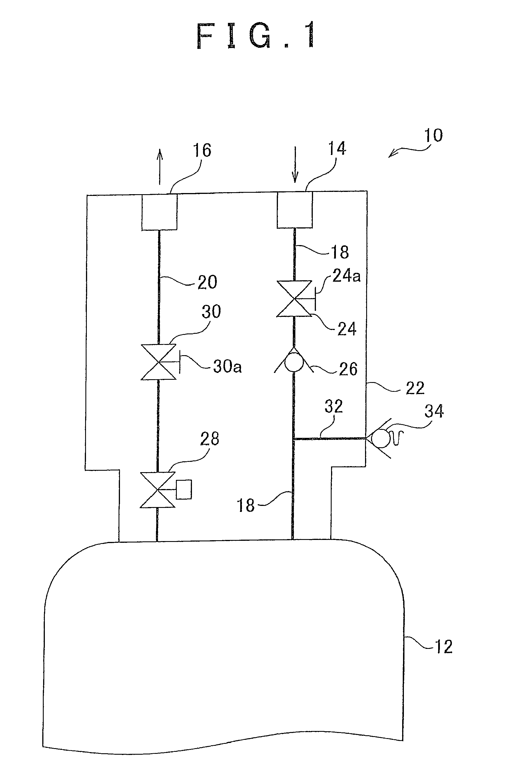
[0029]FIG. 1 illustrates a construction of the valve system of a high pressure tank for a vehicle according to the first embodiment of the present invention. A valve system 10 is mounted to a high pressure tank 12 at an axial end of the tank 12. The high pressure tank 12 is formed into a cylindrical shape to disperse pressure of gas that is...

second embodiment

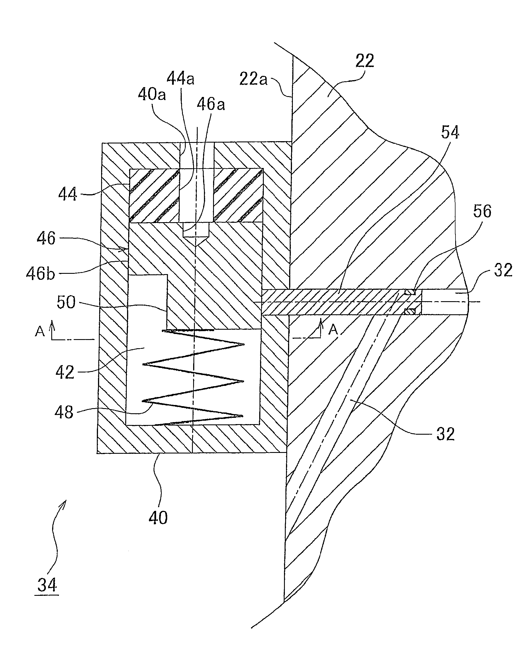
[0060]According to the present invention, a container chamber 42 is opened to the outside at its axial one end. A main body 60 of the fusible plug valve 34 is contained in the container chamber 42, and is screw-joined to an inner wall of a cylindrical part of the container chamber 42. Thus, the main body 60 is rotated with respect to a housing 40, thereby to move the main body 60 advanceably and retractably in the axial direction of the container chamber 42. The main body 60 has an inner cylindrical space. In the inner cylindrical space, a fusible plug 44 and a pin 46 are contained. The main body 60 also has an engaging hole (not shown) in which the manual moving mechanism is engaged. The main body 60 further has a through hole 60a that runs through from the container chamber 42 to the outside on the axis of the container chamber 42. The through hole 60a is designed to discharge the fusible plug 44 that is fused at a high temperature to the outside.

[0061]According to the first embod...


PUM


Abstract

A valve system includes a fusible plug valve that functions as a fusible plug valve and as a manual valve. When functioning as a fusible plug valve, the fusible plug valve opens at a high temperature to release gas from a high pressure tank to outside. When functioning as a manual valve, the fusible plug valve is opened manually to release the gas from the high pressure tank to the outside.

Description

FIELD OF THE INVENTION[0001]The present invention relates to a valve system structure of a high pressure tank for a vehicle.BACKGROUND OF THE INVENTION[0002]A known fuel cell vehicle runs on electric power that is generated in a fuel cell. The fuel cell is supplied with fuel, such as hydrogen gas, to generate the electric power. Such fuel cell vehicle normally has a high pressure tank that contains the fuel under high pressure to be used for the fuel cell. A valve system is mounted to a mouthpiece of the high pressure tank. The valve system has a gas flow passage and various valves that are located on the gas flow passage. The gas flow passage and the various valves are integrated together into the valve system.[0003]Japanese Patent Application Publication No. 2006-242225 (JP-A-2006-242225) discloses a valve system for a gas container. The valve system has a first passage and a second passage that communicate the gas container with the outside. The first passage is designed to flow ...

Claims


Application Information

Patent Timeline
Patent Type & Authority Patents(United States)
IPC IPC(8): F16K17/38F17C13/12F17C13/04F17C7/00
CPCF16K1/307F16K17/383Y10T137/1987Y10T137/7837Y10T137/1797F17C13/04F17C2201/0109F17C2201/056F17C2205/0317F17C2205/0326F17C2205/0329F17C2221/012F17C2223/0123F17C2223/038F17C2260/018F17C2260/042F17C2270/0168F17C2205/0385
Inventor ISHITOYA, TSUKUOOKAWACHI, EIJINUMAZAKI, KAZUSHIKONDO, HISANORIKOIDE, KOJI
Owner TOYOTA JIDOSHA KK
Why Eureka
Try Eureka