Reinforced insulated concrete form

a technology of reinforced concrete and insulated concrete, which is applied in the field of reinforced insulated concrete forms, can solve the problems of insufficient strength of the form system to build a form, cold joints between, and several common problems of insulated concrete form systems, so as to improve the resistance to abrasion and corrosive action, increase the strength, and reduce the cos

Active Publication Date: 2013-10-15
CIUPERCA ROMEO ILARIAN
View PDF139 Cites 65 Cited by
  • Summary
  • Abstract
  • Description
  • Claims
  • Application Information

AI Technical Summary

Benefits of technology

[0025]Another object of the present invention is to provide an insulated concrete form system that is relatively easy to manufacture and / or to assemble.
[0032]Still another object of the present invention is to provide a system for curing of concrete that result in concrete with increased strength, durability and resistance to abrasion.
[0033]Another object of the present invention is to provide an insulated concrete form system that keeps concrete moist, by preventing the loss of moisture from the concrete during the period in which it is gaining strength and durability.
[0034]Still another object of the present invention is to provide an insulated concrete form system that produces hard, dense concrete with improved resistance to abrasion and corrosive actions in addition to minimizing shrinkage and permeability of the concrete.
[0035]Another object of the present invention is to provide an insulated concrete form system that provides improved temperature stability for the curing of concrete.
[0036]A further object of the present invention is to provide an insulated concrete form system that permits the placement of concrete during cold weather which thereby allows construction projects to proceed rather than be shutdown due to inclement weather.

Problems solved by technology

Such prior art insulated concrete form systems suffer from several common problems.
Such form systems are not strong enough to build a form more than a few feet high.
Such systems result in cold joints between the various concrete layers necessary to form a floor to ceiling wall or a multi-story building.
This generally limits current use of insulated concrete forms to buildings of a single story or two in height or to infill wall applications.
Second, the use of multiple form modules to form a wall or other building structure creates numerous joints between adjacent concrete form modules; i.e., between both horizontally adjacent form modules and vertically adjacent form modules.
Thus, the loss of water through leaky joints in adjacent form modules reduces the strength of the concrete.
Third, prior art modular concrete form systems are difficult and time consuming to put together, particularly at a constructions site using unskilled labor.

Method used


Image

  • Reinforced insulated concrete form
  • Reinforced insulated concrete form
  • Reinforced insulated concrete form

Examples


Embodiment Construction

[0086]As used herein, the term “substantially water-proof” means that the insulated concrete form will retain a sufficient amount of water such that the concrete achieves a hardness greater than would be achieved through the use of a conventional concrete form or that an immeasurable amount of water leaks around and / or through the insulated concrete form.

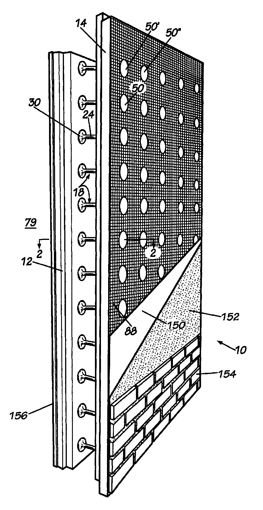
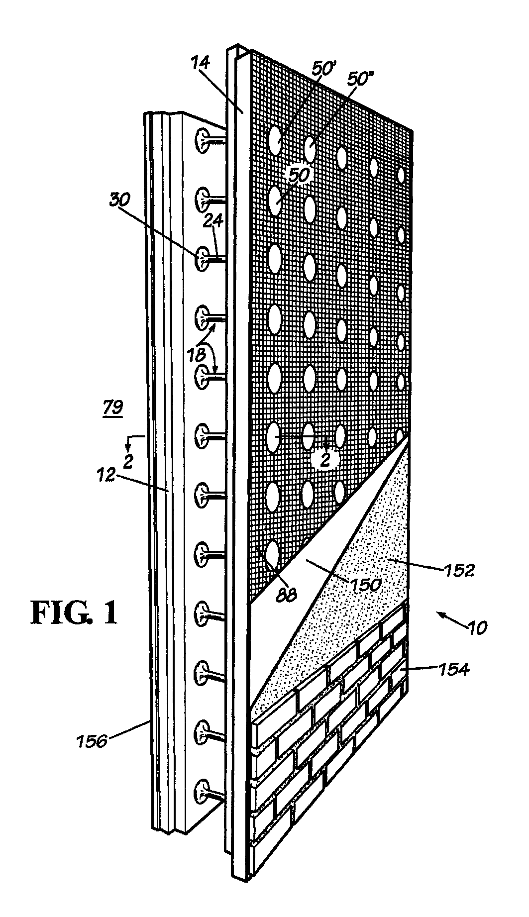
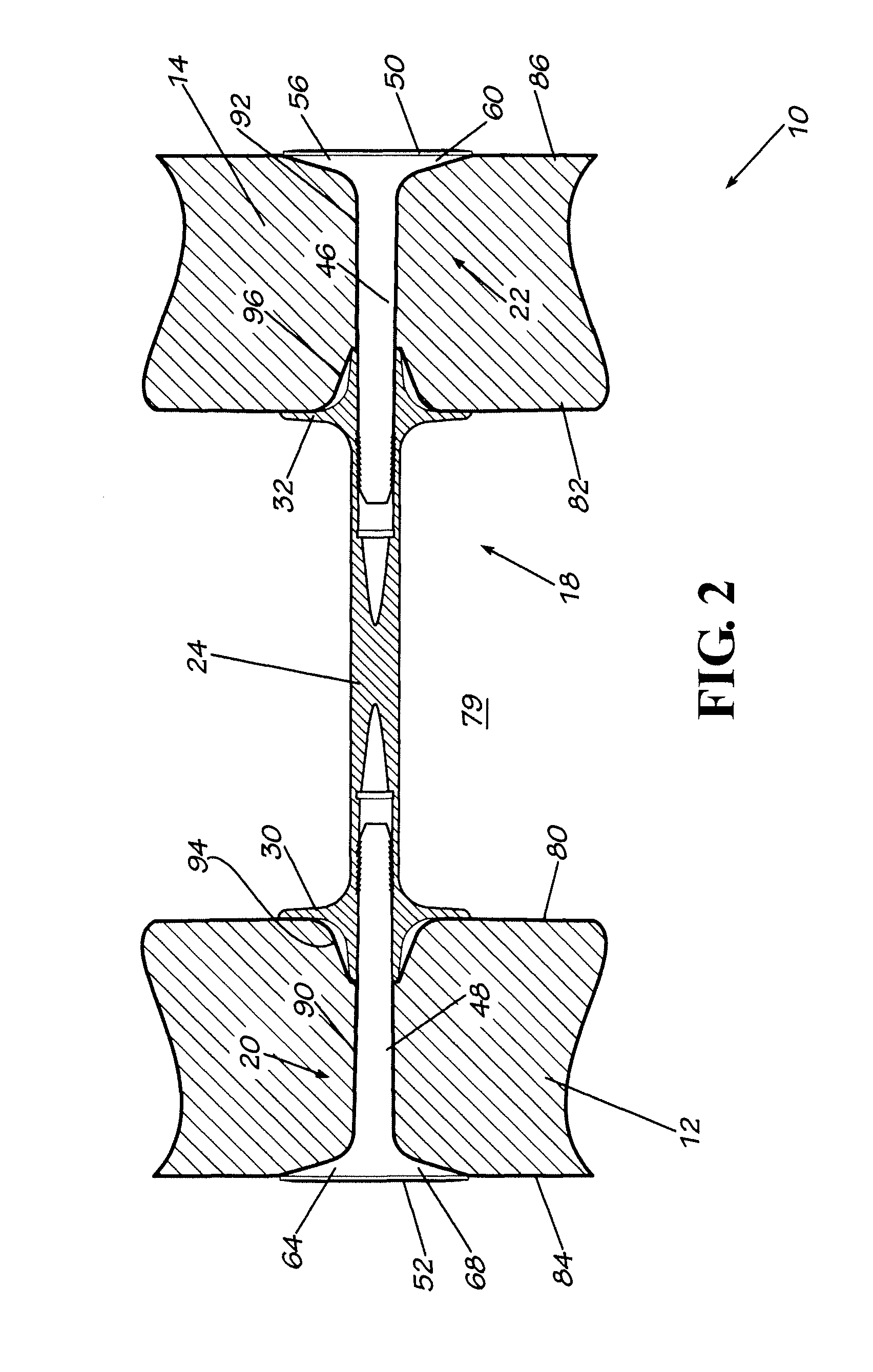
[0087]Referring now to the drawing in which like numbers indicate like elements throughout the several views, there is shown in FIG. 1 a disclosed embodiment of an insulated concrete form 10 in accordance with the present invention. The insulated concrete form 10 includes a first foam insulating panel 12 generally parallel to and spaced apart from a second foam insulating panel 14. The foam insulating panels 12, 14 are preferably made from a polymeric foam material, such as expanded polystyrene. Expanded polystyrene is available under the trademark Neopor® and is available from BASF Corporation, Atlanta, Ga. The foam insulating pane...


PUM

PropertyMeasurementUnit
diametersaaaaaaaaaa
diametersaaaaaaaaaa
thicknessesaaaaaaaaaa

Abstract

The invention comprises a foam insulating panel having an outer surface and a reinforcing member adhered to at least a portion of the outer surface of the foam insulating panel. An insulated concrete form and a method of using the insulated concrete form are also disclosed.

Description

FIELD OF THE INVENTION[0001]The present invention generally relates to insulated concrete forms. More particularly, this invention relates to an insulated concrete form that is stronger than conventional insulated concrete forms so that it can extend from floor to ceiling. The present invention also relates to an insulated concrete form that is easier to make and easier to use. The present invention also relates to methods of using the insulated concrete form of the present invention.BACKGROUND OF THE INVENTION[0002]Concrete walls and other concrete structures have traditionally been made by building a form. The forms were usually made from plywood, wood, metal and other structural members. Unhardened concrete was poured into the form space defined by opposed spaced forms. Once the concrete hardened, the forms were removed leaving a concrete wall or other concrete structure or structural member. The exposed concrete wall is exposed to the elements and subject to curing. Several diff...

Claims


Application Information

Patent Timeline
Patent Type & Authority Patents(United States)
IPC IPC(8): E04B2/30E04G17/06
CPCB23P11/00E04B2/44E04C2/20E04B2/8647F16B19/004F16B21/086E04C2/288F16B5/065E04F13/00E04B1/161Y10T156/1057F16B21/071Y10T29/49826Y10T156/10E04G17/0658E04B2/8617E04C5/07E04G9/05E04G11/06
Inventor CIUPERCA, ROMEO ILARIAN
Owner CIUPERCA ROMEO ILARIAN
Why Eureka
Try Eureka