Arrangement to compensate a non-uniform air gap of an electric machine

a technology of electric machines and air gaps, which is applied in the field of arrangement to compensate non-uniform air gaps of electric machines, can solve the problems of difficult to keep the air gap constant or at least nearly constant, require very rigid, massive and heavy support structures, and reduce the risk of rotor arrangement hitting the stator arrangement during the operation, and reduce the negative effect of non-uniform air gap or even elimination

Active Publication Date: 2013-10-15
SIEMENS GAMESA RENEWABLE ENERGY AS
View PDF28 Cites 31 Cited by
  • Summary
  • Abstract
  • Description
  • Claims
  • Application Information

AI Technical Summary

Benefits of technology

[0059]On the other hand the effectiveness of the electrical machine is increased as the negative effects of the non-uniform air gap are reduced or even eliminated.

Problems solved by technology

For generators, like direct drive or directly driven generators, this is very difficult due to their size.
Especially for a direct drive generator it is difficult to keep the air gap in a range of only a few millimeters.
This requires therefore very rigid, massive and heavy support structures for the stator elements and for the rotor elements.
Due to the one-sided support of the stator it is difficult to keep the air gap constant or at least nearly constant.
If they are applied to a direct-drive-generator of a wind turbine there is a high probability that the air gap is not uniform any more.
Thus a non-uniform air gap might be the result.

Method used


Image

  • Arrangement to compensate a non-uniform air gap of an electric machine
  • Arrangement to compensate a non-uniform air gap of an electric machine
  • Arrangement to compensate a non-uniform air gap of an electric machine

Examples


Embodiment Construction

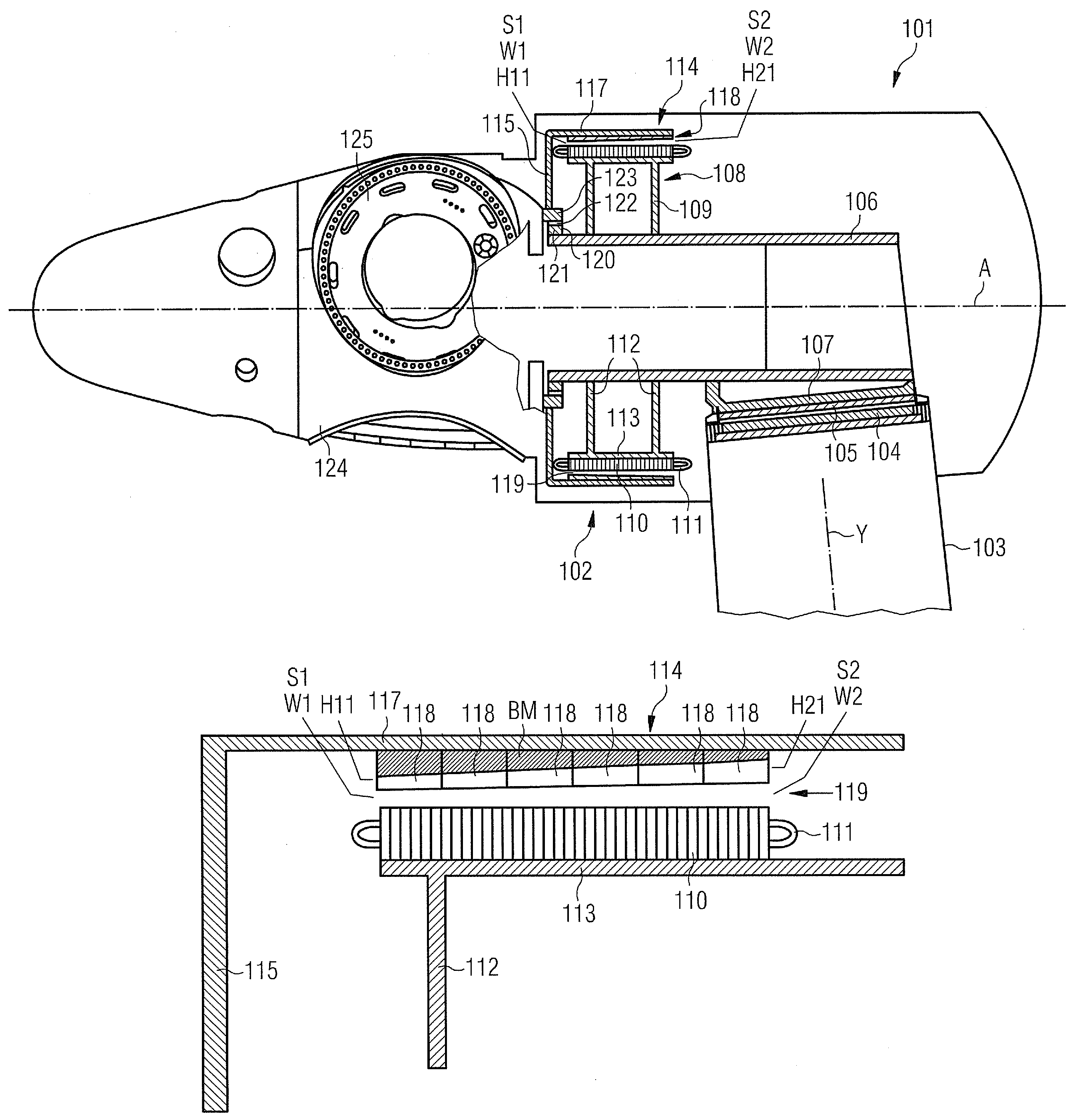
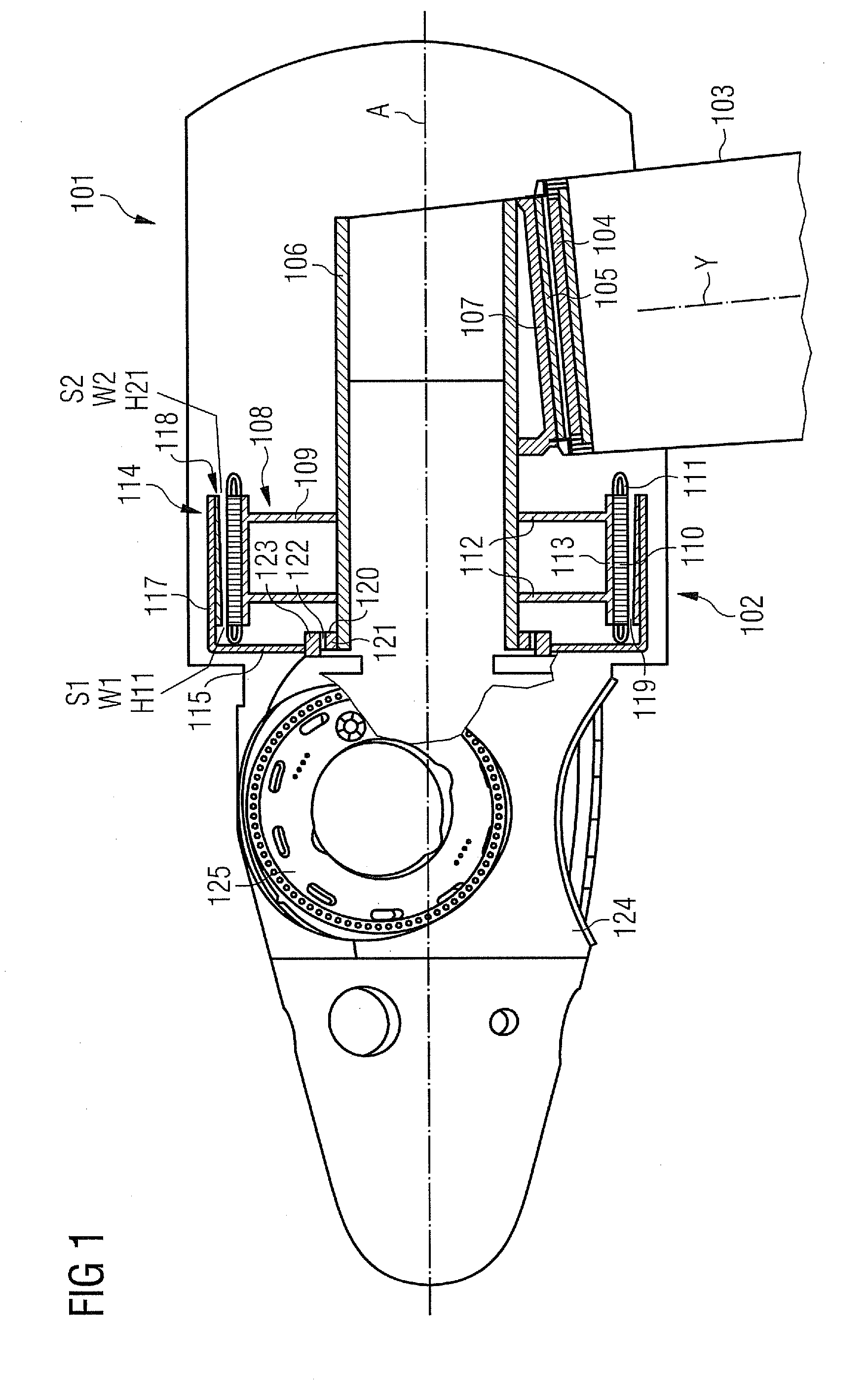
[0064]A wind turbine 101 comprises a direct drive generator 102, which is arranged on the upwind side of a tower 103 of the wind turbine 101.

[0065]A tower flange 104 is arranged on the top of the tower 103. A bedplate 105 is attached to the tower flange 104. The wind turbine 101 comprises a yaw system—not shown here—which is used to turn the bedplate 105 of the wind turbine 101 around the axis Y.

[0066]The wind turbine 101 comprises a stationary shaft 106, while the shaft 106 has a centre axis A. The rear side of the stationary shaft 106 is attached to a retaining arrangement 107. On the front side of the stationary shaft 106 a stator arrangement 108 of the direct drive generator 102 is arranged.

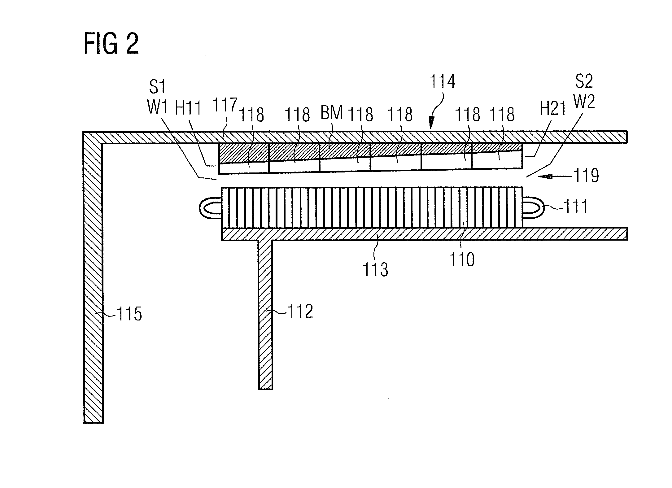
[0067]The stator arrangement 108 comprises a stator support structure 109 and a lamination stack 110. The lamination stack 110 supports at least one winding 111.

[0068]The stator support structure 109 comprises two support elements 112 for a two side support of the lamination stack 110. The su...


PUM


Abstract

An arrangement to compensate a non-uniform air gap, which is located in an electric machine is provided. The electrical machine includes a stator arrangement and a rotor arrangement. The rotor arrangement rotates around a longitudinal axis. At least parts of the rotor arrangement interact with parts of the stator arrangement to generate electrical power. The air gap is defined by the distance between the parts of the rotor arrangement and the parts of the stator arrangement. The parts of the stator arrangement are opposite to the parts of the rotor arrangement along a certain length. The cross section of the air gap changes along this length thus the air gap is not uniform in view to the referred certain length. The flux density of magnets, which are part of the rotor arrangement, is changed in dependency to the cross section of the air-gap.

Description

CROSS REFERENCE TO RELATED APPLICATIONS[0001]This application claims priority of European Patent Office application No. 09015204.2 EP filed Dec. 8, 2009, which is incorporated by reference herein in its entirety.FIELD OF INVENTION[0002]The invention relates to an arrangement to compensate a non-uniform air gap, which is located in an electric machine. The invention especially relates to a compensation of an air-gap, which is between a rotor and a stator of a generator.BACKGROUND OF INVENTION[0003]Preferably the electrical machine is a generator like a “direct drive” generator used in a wind turbine.[0004]Each generator shows an air gap, which is located between stator elements and rotor elements of the generator.[0005]The rotor elements contain permanent magnets for example, while the stator elements contain stacked laminate plates, which support at least one winding of the stator coil.[0006]The air gap should be relatively small to ensure a high efficiency of the generator. Thus th...

Claims


Application Information

Patent Timeline
Patent Type & Authority Patents(United States)
IPC IPC(8): H02K21/12H02K5/16
CPCH02K1/2786H02K7/1838H02K7/085H02K2201/03Y02E10/725Y02E10/72H02K1/2791
Inventor STIESDAL, HENRIK
Owner SIEMENS GAMESA RENEWABLE ENERGY AS
Why Eureka
Try Eureka