
Angled on-board injector

a technology of injector and cylinder head, which is applied in the direction of machines/engines, stators, liquid fuel engines, etc., can solve the problems of complicated packaging of secondary flow systems, and achieve the effect of reducing losses, minimizing radial height and axial spacing

Active Publication Date: 2013-10-22
RTX CORP
View PDF30 Cites 26 Cited by
  • Summary
  • Abstract
  • Description
  • Claims
  • Application Information

AI Technical Summary

Benefits of technology

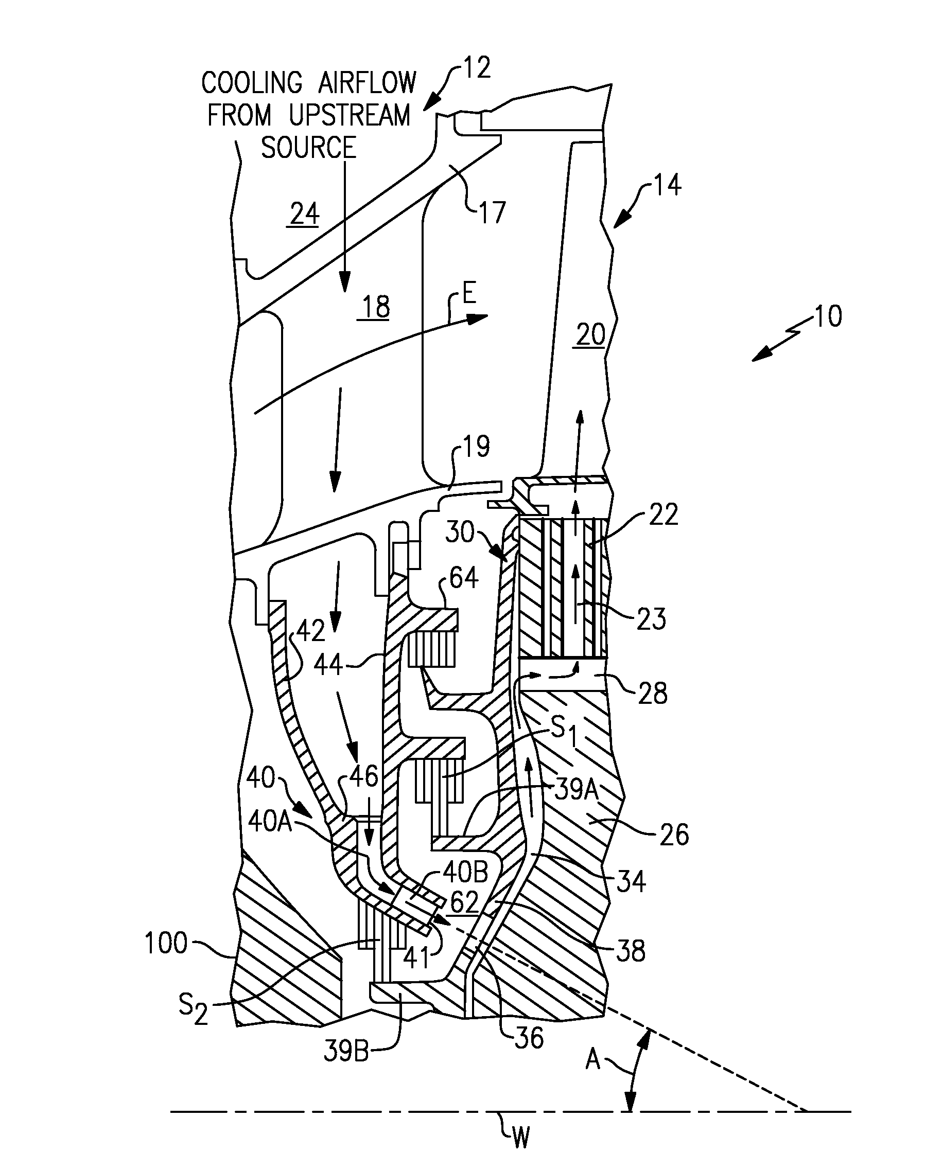
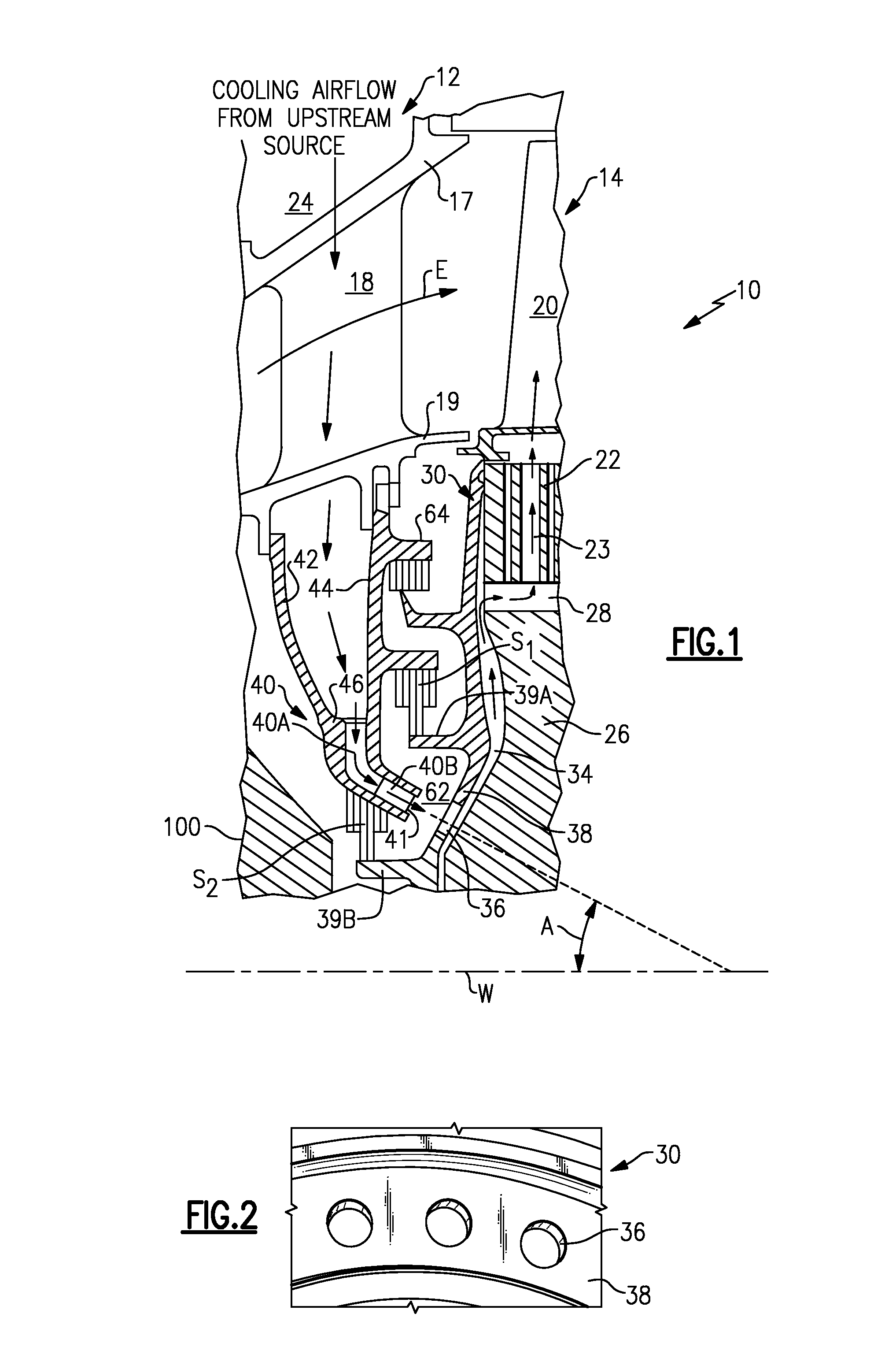
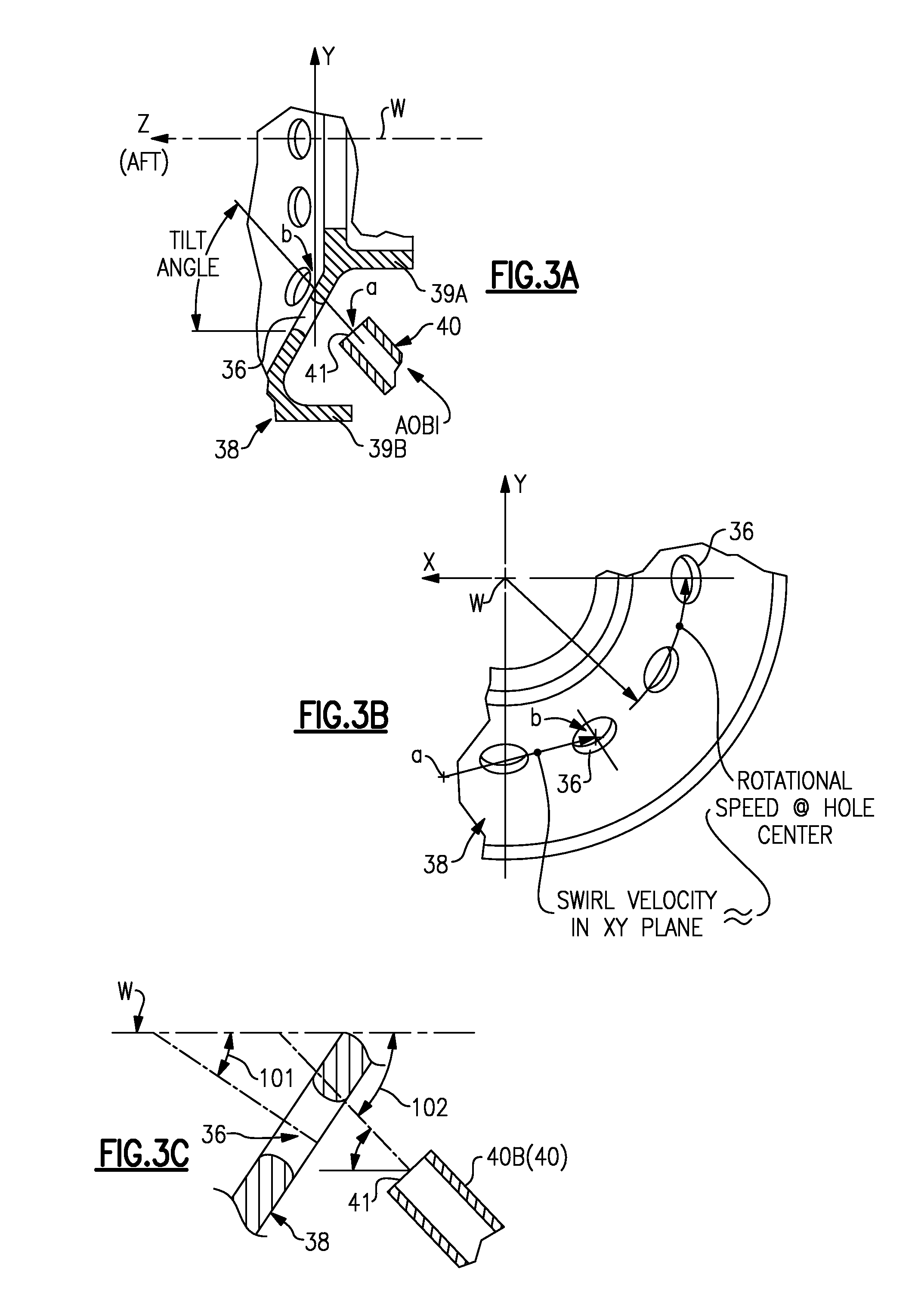
[0007]The secondary flow system according to the present invention provides a compact injector cooling structure for a gas turbine engine that includes an Angled On-board Injector (AOBI) to locate a metering throat at an inward angle relative to an engine centerline.
[0009]The angled annular section is located at a corresponding angle relative the engine centerline such that the angled annular section is generally transverse to the AOBI nozzle. The AOBI allows for a flexible design which can be optimized such that the axial and radial packaging is minimized. The angled annular section may thereby be located at a smaller radius verses a TOBI to conserve radial height. Because the AOBI is angled inward, the intersection of the flow with the turbine rotor coverplate inlet feature also requires less radial spacing than a traditional TOBI. The AOBI creates additional design flexibility when aligning the nozzle discharge to the holes in the coverplate. Furthermore, the AOBI is located at a relatively small radius with the resulting benefit of lower cavity pressure.
[0011]The present invention therefore provides a compact injector cooling structure for a relatively small gas turbine engine which transfers cooling air from stationary cavities within a turbine stator assembly to a turbine rotor assembly thereof, yet minimizes the required radial height and axial spacing and lowers losses therefrom.

Problems solved by technology

Packaging of a secondary flow system may be particularly complicated, as conventional Tangential On-Board Injectors (TOBI) or Radial On-Board Injectors (ROBI) require a radial height and seal structure that may be incompatible with such relatively small packaging requirements.

Method used


Image

  • Angled on-board injector
  • Angled on-board injector
  • Angled on-board injector

Examples


Embodiment Construction

[0018]FIG. 1 schematically illustrates a simplified portion 10 of the turbine section of a gas turbine engine. Included within the portion shown is a turbine stator assembly 12 and a turbine rotor assembly 14. A flow path E for combustion gases is provided downstream of a combustion chamber (not shown) and defined in part by the stator assembly 12 including an annular outer flow path wall 17 and an annular inner flow path wall 19. The flow path E extends generally axially between alternating rows of stator vanes which form a stator vane section as represented by the single vane 18, and rows of rotor blades which form a rotor blade section as represented by the single blade 20. An annular cavity 24 is formed within the stator assembly 12 and it functions in part as a reservoir for turbine cooling air.

[0019]Downstream of the row of stator vanes 18 is disposed the row of rotor blades 20. The rotor blades 20 extend radially outwardly from a supporting rotor disk 26 via respective rotor ...


PUM


Abstract

A secondary flow system provides a compact injector cooling structure for turbine blades which includes an Angled On-board Injector (AOBI) that locates a metering throat at an inward angle relative to an engine centerline. The AOBI positions the metering throat at the inward angle relative to an engine centerline to communicate cooling airflow to an angled annular section of a turbine rotor disk coverplate.

Description

BACKGROUND OF THE INVENTION[0001]The present invention relates to a gas turbine engine cooling structure that provides a cooling air flow to turbine blades, and more particularly to an Angled On-Board Injector (AOBI) that locates a metering throat at an inward angle relative to an engine centerline.[0002]In gas turbine engines, fuel is burned within a combustion chamber to produce hot gases of combustion. The hot gases are expanded within a turbine section to produce a gas stream across alternating rows of stationary turbine stator vanes and rotating turbine rotor blades to produce power. Turbine blades and vanes are cooled by air compressed upstream within the engine and flowed to the turbine section through a secondary flow system.[0003]Secondary flow systems transfer cooling air which bypasses the combustor from stationary cavities within the engine stator to a turbine rotor assembly for subsequent distribution to the interior of the rotor blades. For this purpose, the tangential...

Claims


Application Information

Patent Timeline
Patent Type & Authority Patents(United States)
IPC IPC(8): F01D25/12F01D9/06
CPCF01D5/081F01D5/082F02C7/28F05D2240/56F05D2260/60F05D2250/314
Inventor MCCAFFREY, MICHAEL G.CAPRARIO, JOSEPH T.ALLEN, GEORGE E.MOORE, CHRISTOPHERGAGNON, RONALD R.
Owner RTX CORP
Learn More