
Near field RF communicators and near field RF communications-enabled devices

a technology of near field rf communication and communication channel, which is applied in the direction of near-field systems using receivers, transmission monitoring, instruments, etc., can solve the problems of difficult to adjust the dynamic range of the circuit as regards received signals, significant reduction in the q of the antenna circuit, and inability to maximize the modulated carrier signal. , to achieve the effect of minimising overloading and less noise-sensitiv

Active Publication Date: 2013-10-22
NXP USA INC
View PDF10 Cites 19 Cited by
  • Summary
  • Abstract
  • Description
  • Claims
  • Application Information

AI Technical Summary

Benefits of technology

The present invention provides a way to reduce the impact of noise and overvoltage damage in near field RF communicators. This is achieved by using low impedance demodulator inputs and increasing the modulated carrier signal input without the need for high input impedance voltage couplings. This also allows for easier adjustment of the dynamic range and minimization of overloading. Overall, this results in more reliable and efficient RF communication.

Problems solved by technology

However with existing designs the demodulator inputs tend to be high impedance and this can lead to a significant reduction in the Q of the antenna circuit and inability to maximize the modulated carrier signal being input to the demodulator.
This limitation on the maximum voltage which can be allowed to develop at the antenna coil makes it difficult to adjust the dynamic range of the circuit as regards received signals.

Method used


Image

  • Near field RF communicators and near field RF communications-enabled devices
  • Near field RF communicators and near field RF communications-enabled devices
  • Near field RF communicators and near field RF communications-enabled devices

Examples


Embodiment Construction

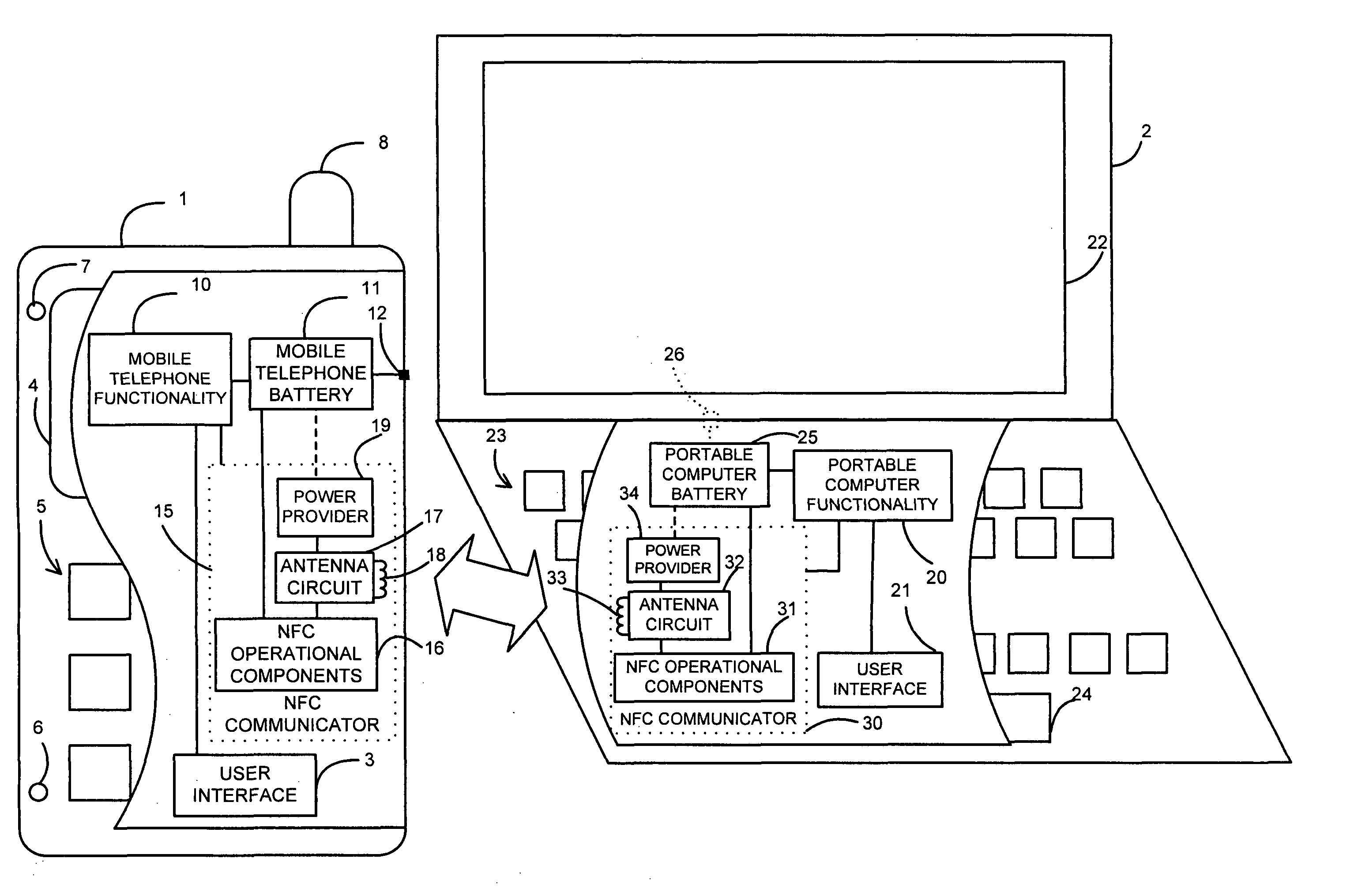
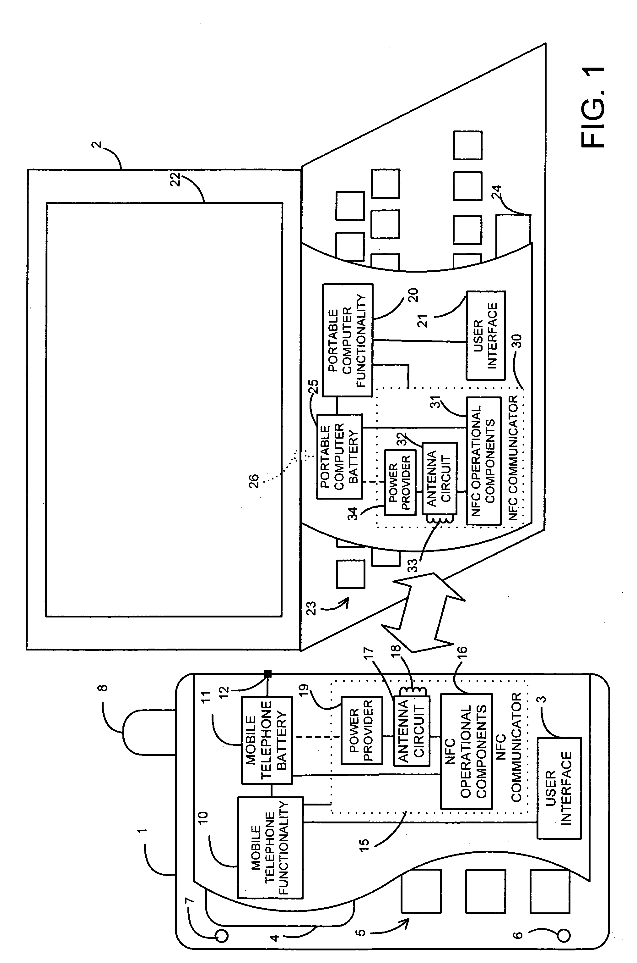
[0028]Referring now specifically to FIG. 1, there is shown a representational diagram illustrating communication between two NFC communications-enabled devices. In FIG. 1 the representations of the NFC communications-enabled devices have been shown partly cut-away and the functionality provided by the NFC communications-enabled devices illustrated by way of a functional block diagram within the NFC communications-enabled device.

[0029]As shown in FIG. 1, one NFC communications-enabled device comprises a mobile telephone (cellular telephone, “cellphone”) 1 and the other NFC communications-enabled device comprises a portable computer 2 such as a notebook or laptop computer.

[0030]The mobile telephone 1 has the usual features of a mobile telephone including mobile telephone functionality 10 (in the form of, usually, a programmed controller, generally a processor or microprocessor with associated memory or data storage, for controlling operation of the mobile telephone in combination with...


PUM


Abstract

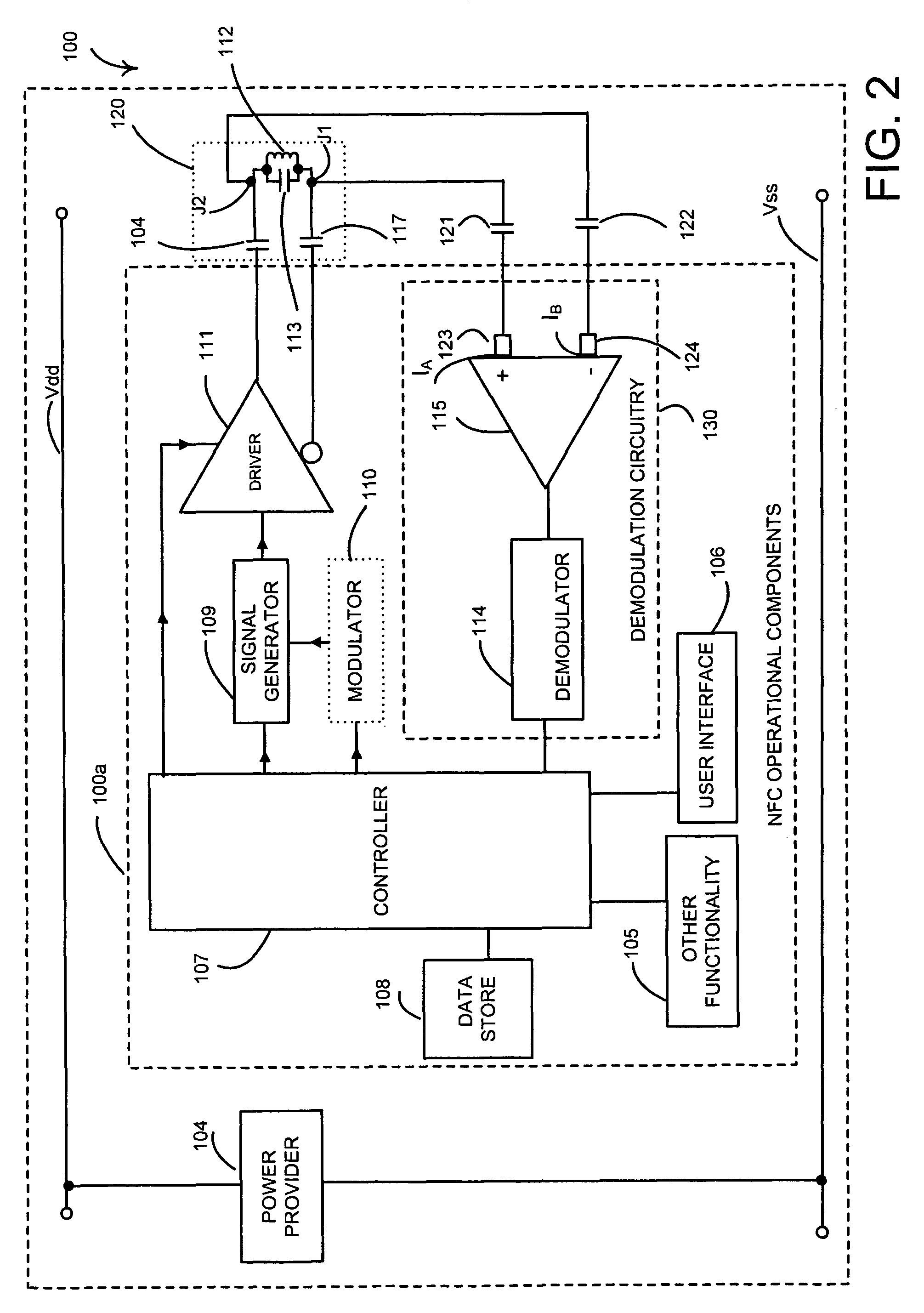
A near field RF communicator has an antenna circuit (120) to receive a modulated radio frequency signal by inductive coupling and demodulation circuitry (130 or 131) to extract the modulation from a received modulated radio frequency signal inductively coupled to the antenna circuit. The demodulation circuitry has a virtual earth input comprising a current mirror. The demodulation circuitry may be formed by an amplifier (115 or 116) and a demodulator (114) coupled to an output of the amplifier. The amplifier may be a single input amplifier (116) coupled to an output of the antenna circuit or may be a differential amplifier (115) having first and second inputs to receive the modulated radio frequency signal from first and second outputs of the antenna circuit, with each amplifier input providing a virtual earth input.

Description

CROSS REFERENCE TO RELATED APPLICATIONS[0001]This application is a national stage application under 35 U.S.C. §371 of International Application No. PCT / GB2007 / 004528, filed Nov. 27, 2007, which claims the priority of United Kingdom Application No. 0623653.3, filed Nov. 27, 2006, the contents of which are herein incorporated by reference.FIELD OF THE INVENTION[0002]This invention relates to near field RF communicators and near field RF communications-enabled devices.BACKGROUND OF THE INVENTION[0003]Near field RF (radio frequency) communication requires an antenna of one near field RF communicator to be present within the alternating magnetic field (H field) generated by the antenna of another near field RF communicator by transmission of an RF signal (for example a 13.56 Mega Hertz signal) to enable the magnetic field (H field) of the RF signal to be inductively coupled between the communicators. The RF signal may be modulated to enable communication of control and / or other data. Ran...

Claims


Application Information

Patent Timeline
IPC IPC(8): H04B5/00
CPCG06K7/0008G06K7/10237H04B5/02H04B5/0062H04B5/0081H04B5/77H04B5/26H04B5/48G06K19/0723G06K19/073H03D1/18H03D3/00H03D3/001H04B5/00
Inventor BANGS, JOAKIMMILES, DAVID
Owner NXP USA INC
Learn More