Magnetic device for damping blade vibrations in turbomachines

a technology of magnetism and vibration damping, which is applied in the field of magnetism for damping blade vibration in turbomachines to achieve the effect of high damping values

Inactive Publication Date: 2013-10-29
SIEMENS AG
View PDF14 Cites 9 Cited by
  • Summary
  • Abstract
  • Description
  • Claims
  • Application Information

AI Technical Summary

Benefits of technology

[0027]A further advantage of the invention is that it can be used with titanium blades. Furthermore, the device according to the invention is very effective, wherein high damping values can be achieved.
is that it can be used with titanium blades. Furthermore, the device according to the invention is very effective, wherein high damping values can be achieved.

Problems solved by technology

A movement of the induction plate as a result of this magnetic field induces eddy currents in the induction plate which results in development of an opposing magnetic field, which, according to Lenz's law, is formed in opposition to the external magnetic field, which gives rise to an opposing force which leads ultimately to damping.

Method used


Image

  • Magnetic device for damping blade vibrations in turbomachines
  • Magnetic device for damping blade vibrations in turbomachines
  • Magnetic device for damping blade vibrations in turbomachines

Examples


Embodiment Construction

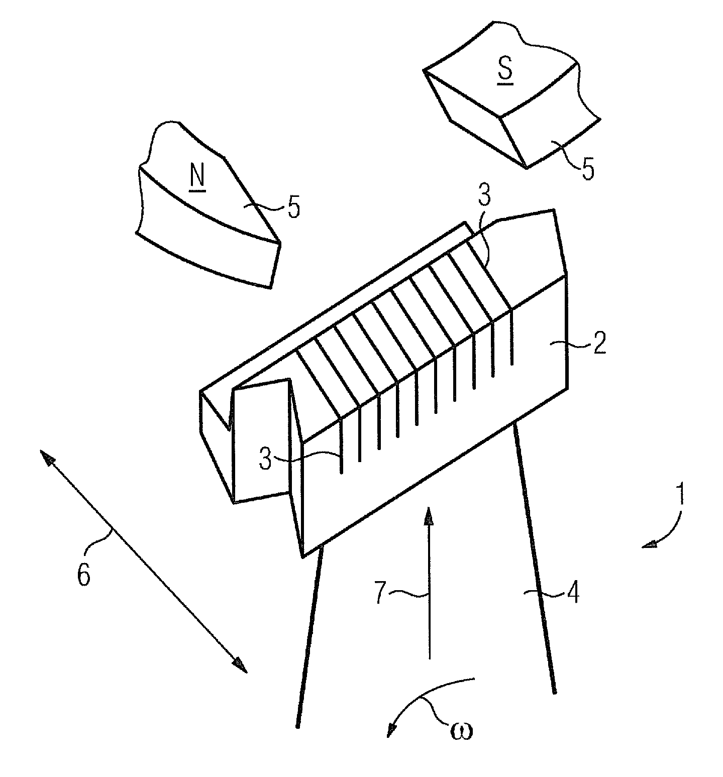
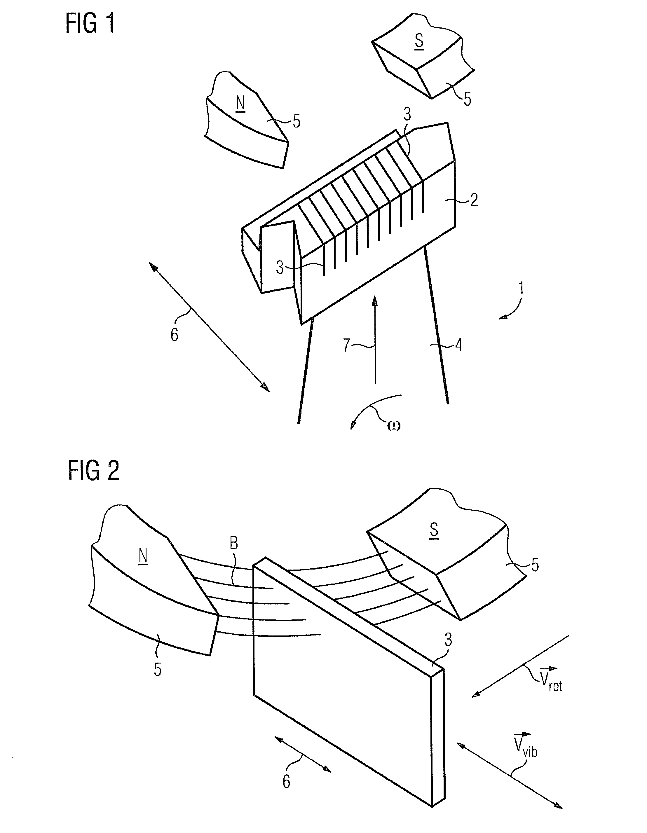
[0041]FIG. 1 shows a blade 1. This blade 1 can be a turbine blade or a compressor blade. The blade 1 is arranged on a rotor, which is not shown. The arrangement consisting of rotor and blade 1 is rotatably mounted around a rotational axis 23 which is not shown in FIG. 1. During operation, a rotation around this rotational axis 23 is executed at a rotational frequency ω. The principal movement of the blade 1 extends along the rotor orbit. An undesirable movement which is superimposed upon these principal movements is the vibration of the blade 1. These disturbing vibrations can be damped by means of eddy currents. The arrangement of the induction plates 3 and of the magnetic field result in no force components, which brake the principal movement, being created since these brake the motor.

[0042]The blade 1 has a shroud 2 in which induction plates 3 are arranged. The shroud 2 is arranged on a blade airfoil 4. The rotor, with the blades 1, is rotatably mounted in a turbomachine, which i...


PUM


Abstract

An arrangement for damping blade vibrations in a turbomachine is provided. The blade vibrations are due to an arrangement made of magnets and multiple induction plates and the undesired vibrations of the blade are damped by creating turbulent flows, wherein the induction plates are directed parallel to the rotation axis, and the magnetic field caused by the magnets is formed homogenously in the circumferential direction.

Description

CROSS REFERENCE TO RELATED APPLICATIONS[0001]This application is the US National Stage of International Application No. PCT / EP2008 / 066156, filed Nov. 25, 2008 and claims the benefit thereof. The International Application claims the benefits of European Patent Office application No. 07024982.6 EP filed Dec. 21, 2007. All of the applications are incorporated by reference herein in their entirety.FIELD OF INVENTION[0002]The invention refers to a turbomachine, especially to a steam turbine, comprising a turbine blade which is rotatably arranged around a rotational axis and oriented along a blade axis, a housing which is arranged around the turbine blade, an induction plate which is arranged in the turbine blade tip, and a magnet which is arranged in the housing.BACKGROUND OF INVENTION[0003]Water turbines, steam and gas turbines, windmills, centrifugal pumps and centrifugal compressors, and also propellers, are classified under the collective term turbomachines. Common to all these machi...

Claims


Application Information

Patent Timeline
Patent Type & Authority Patents(United States)
IPC IPC(8): F03D11/00
CPCF01D5/225F01D5/26F01D25/06F05D2300/507
Inventor RICHTER, CHRISTOPH HERMANN
Owner SIEMENS AG
Why Eureka
Try Eureka