See-through optical system

a technology of optical systems and optical beams, applied in the field of see-through optical beams, can solve the problems of inefficient system light management, limited system efficiency, and inability to fully utilize the area inside the existing periscope to collimate images, and achieve the effect of reducing the reflection of beacons

Inactive Publication Date: 2013-10-29
WEISSMAN PAUL
View PDF9 Cites 184 Cited by
  • Summary
  • Abstract
  • Description
  • Claims
  • Application Information

AI Technical Summary

Benefits of technology

The patent describes a method for designing optical systems that allows certain parts to be used for multiple purposes and can transmit light in multiple directions. This design creates smaller and stronger optical systems.

Problems solved by technology

These inventions do not make full use of the area inside an existing periscope to collimate the image.
The efficiency of the system is limited by the reflectance of the beam-splitter 13 times the reflectance of the curved mirror 19 times the transmission of beam splitter 13.
Prior art device 300 suffers from (1), the curved beam-splitter 304 requires a relatively large volume, and (2) the system is inefficient in light management.

Method used


Image

  • See-through optical system
  • See-through optical system
  • See-through optical system

Examples


Embodiment Construction

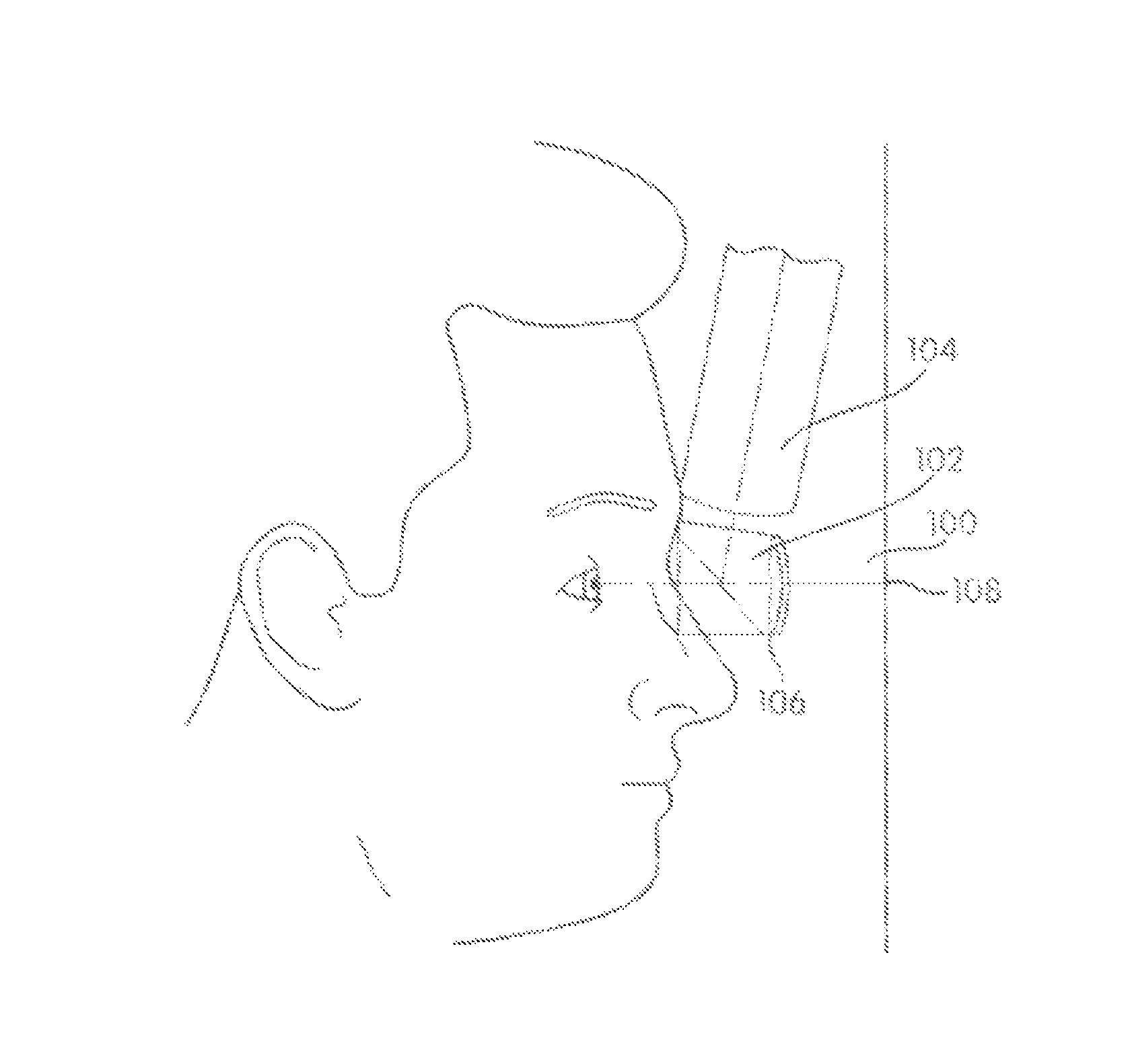
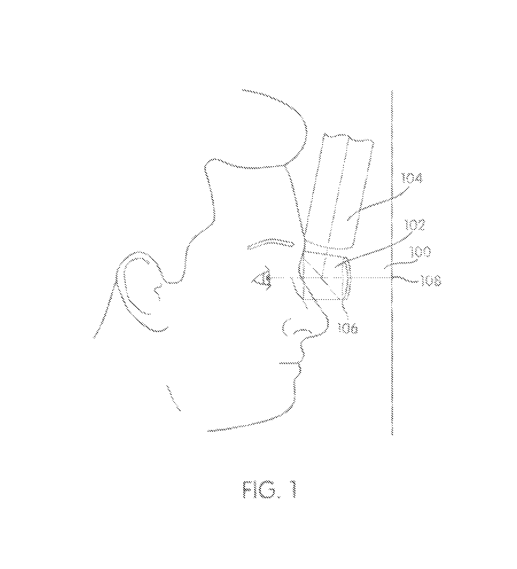
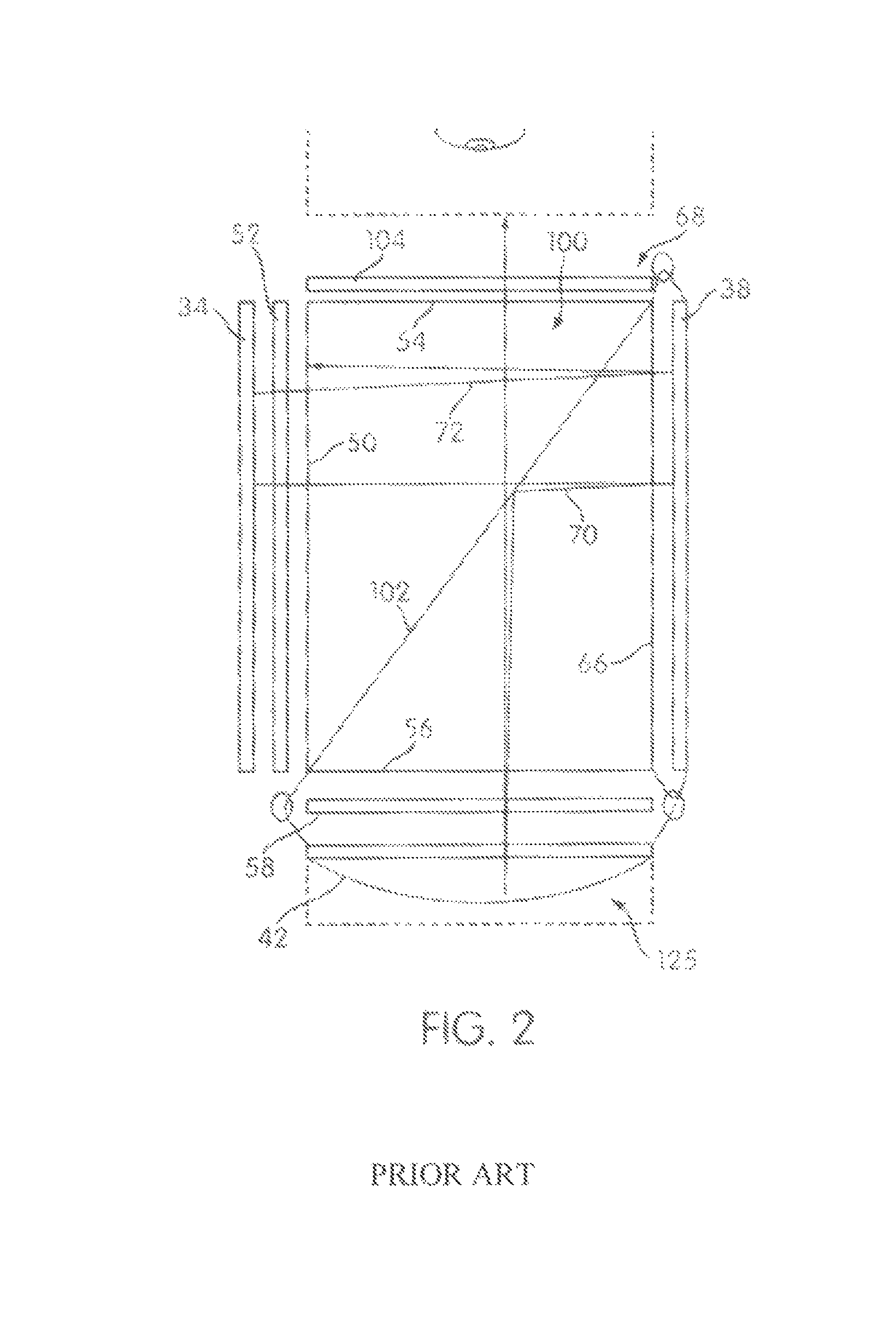
[0030]The current invention is an optical assembly which has two optical paths which may be used independently or combined. The first optical path directs light from the outside world through an optical medium within which a reflective notch non conformal concave reflector, a mirror and a beam splitter are placed forming a rhomboid and in which additional optical elements may be placed such as filters and wave plates. The light from the outside world is viewed by an observer through the rhomboid. The second optical path uses a narrow spectral width and part, or the entire same rhomboid in combination with some, or all of the optical elements and an image source to form a collimated or near collimated image. The collimated or near collimated image is directed from a focal plane within the optical assembly towards a collimating surface within the optical assembly after which the collimated image is directed towards the observer. The two paths combine a narrow band(s) non-conformal col...


PUM


Abstract

The embodiments herein describe how if a narrow wave length notch of light is used to illuminate or create an image source then the beam-splitter is only required to transmit over the narrow wavelength notch. If the concave mirror only reflects the same wavelength notch then all other wavelengths will pass through the mirror and be reflected by the beam-splitter. Each of the embodiments uses a method of optical design wherein certain portions or elements of the optical system are used for multiple purposes and / or transmit certain paths of light transmission in multiple directions. This use of multiple purposes and multiple paths produces embodiments of the invention that are smaller and more robust.

Description

CROSS REFERENCE[0001]This application is related to provisional application Ser. No. 61 / 212,015 filed on Apr. 4, 2009 entitled “A See-Through Optical System and is hereby incorporated herein by reference.GOVERNMENT SUPPORT[0002]Funds for the development of this disclosure were provided under Contract number W91 CRB-08-C-0110 from US Army RDECOM Simulation and Technology Training Center, 12423 Research Parkway. Orlando, Fla. 32826-3274FIELD OF THE INVENTION[0003]The Field of Invention is a see through optical systems in particular, a see through optical system with a specialized beam-splitter or a non-conformal concave reflector or both.BACKGROUND OF THE INVENTION[0004]For many years the applicant has been building optics composed of a beam-splitter cube and a concave reflecting surface. These devices have evolved starting with non-polarized versions through polarized versions. The devices have been used with see through to the outside world as well as immersive only displays.[0005]B...

Claims


Application Information

Patent Timeline
Patent Type & Authority Patents(United States)
IPC IPC(8): G02B27/14
CPCG02B27/283G02B27/0172G02B5/32G02B3/08G02B27/0103
Inventor WEISSMAN, PAUL
Owner WEISSMAN PAUL
Why Eureka
Try Eureka