Check patentability & draft patents in minutes with Patsnap Eureka AI!

Power converter system and method

a power converter and power technology, applied in power conversion systems, control systems, ac-ac conversion, etc., can solve problems such as damage to load or decrease load life expectancy, common mode voltages can become fairly high in amplitude, and can potentially reach levels, and modified power converter designs fail to reduce common mode voltage to satisfactory levels

Active Publication Date: 2013-10-29
ROCKWELL AUTOMATION TECH
View PDF6 Cites 5 Cited by
  • Summary
  • Abstract
  • Description
  • Claims
  • Application Information

AI Technical Summary

Benefits of technology

The solution significantly reduces common mode voltages from potentially damaging levels to safer values, enhancing the reliability and lifespan of loads while maintaining system simplicity and cost-effectiveness.

Problems solved by technology

Under various operating conditions, these common mode voltages can become fairly high in amplitude and can potentially reach levels that are beyond the insulation ratings of the motor windings (or other load rating).
Consequently, running of the load in a manner resulting in such common mode voltages can risk damaging the load or decrease its life expectancy.
However, the modified power converter designs either fail to reduce common mode voltage to satisfactory levels or introduce other disadvantages.
However, such modified power converters are more complicated to operate and control, achieve their results at a cost to the power converters' modulation indices and / or total harmonic distortion levels of voltage and current, and in any event fail to substantially reduce the common mode voltages.
However, the use of additional switches can increase the complexity of controlling operation of the power converters, and can increase the cost of the power converters by increasing the number of circuit components.
Also, the use of such transformers increases the cost of the power converters and, due to the size of the transformers, can increase the bulkiness of the power converters.
Such a provision is not available in a standard power converter.
In particular, this configuration is not applicable to motors with a Delta connected stator windings.

Method used


Image

  • Power converter system and method
  • Power converter system and method
  • Power converter system and method

Examples


Embodiment Construction

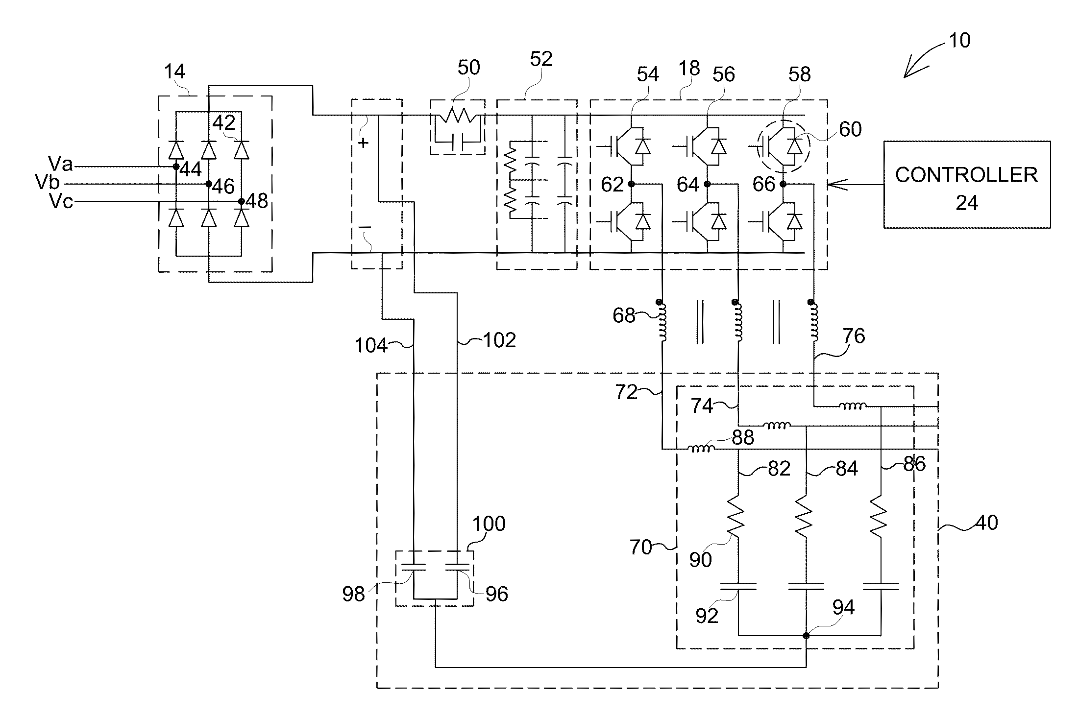
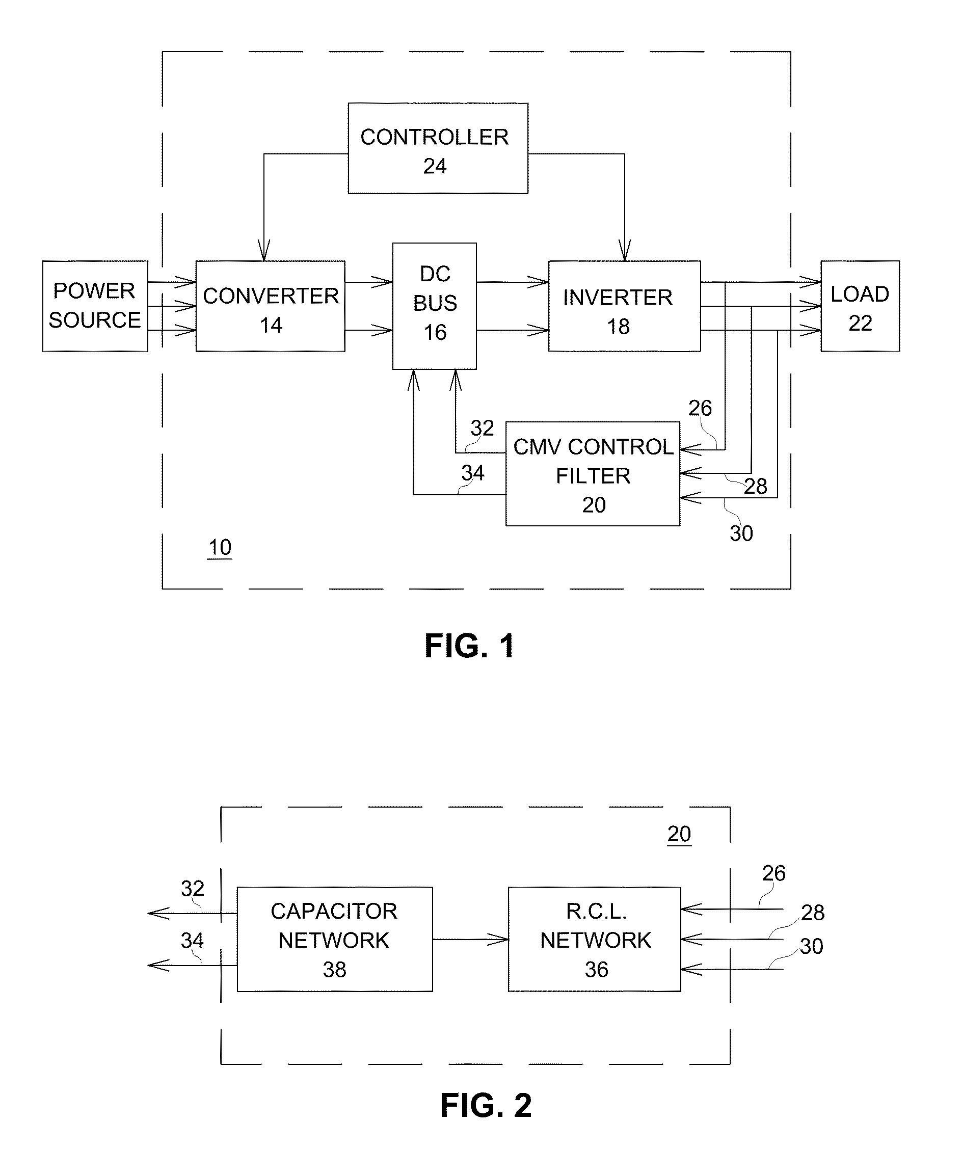
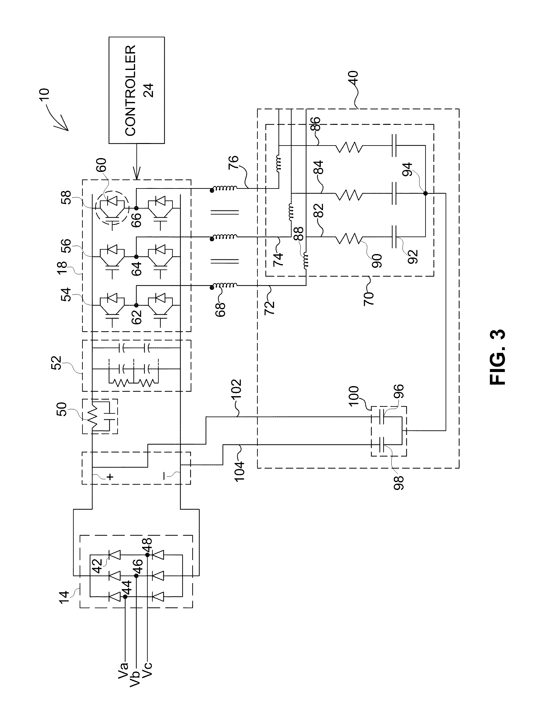
[0022]Turning now to the drawings, and referring first to FIG. 1, a power converter system is illustrated. Power converter system 10 includes a converter 14, a DC bus 16, an inverter 18, a common mode voltage (CMV) control filter 20, and a controller 24. The output of the power converter system is provided to load 22. Each block is described in further detail below.

[0023]Power source 12 provides a three phase input power to the power converter system. The three phase power is provided on three separate input lines as a first, second and third phase to the power converter system 10. Converter14 is configured to convert three phase electrical power into corresponding DC power.

[0024]In one exemplary embodiment, the converter comprises six switching devices. The switches may be active devices such as solid state switches or the converter can be constructed using diodes. For a converter that employs active switches, switching operation is controlled by controller 24. The DC power supply ...


PUM


Abstract

A three-phase power converter includes a converter configured to convert a three phase AC power input to a DC power output, the DC power output being provided to high and low sides of a DC bus, and an inverter coupled to the DC bus and configured to convert the DC power to a three phase AC output. The inverter comprises three legs and each leg comprises a pair of solid state switches and a respective output therebetween. The power converter further includes a common mode voltage control filter comprising three filter inputs and two filter outputs, each filter input coupled to an output of a respective leg of the inverter and each filter output coupled to a respective side of the DC bus.

Description

BACKGROUND[0001]The invention relates to power converter systems and more specifically to a system and method for controlling common mode voltages generated in power converter systems.[0002]Typically, a three phase power converter system includes a power source that generates variable frequency AC input power, a rectifier, an inverter and a load. The rectifier operates to convert the AC input power to corresponding DC power. The inverter operates to convert the DC power to AC output power of a desired frequency. The AC output power is used to drive a load such as a motor.[0003]The rectifier and inverter typically include switching devices such as solid state switches (e.g., insulated gate bipolar transistors) and diodes. In rectifiers or inverters that employ solid state switches, the switching operation is performed in a controlled fashion to obtain a desired output power. The switches may be controlled using a control system, which typically includes a control circuit based on a p...

Claims


Application Information

Patent Timeline
Patent Type & Authority Patents(United States)
IPC IPC(8): H02M1/12H02M5/45
CPCH02M5/458H02P2209/01H02M1/126H02M1/123
Inventor SKIBINSKI, GARY L.AHMED, AHMED MOHAMED SAYED
Owner ROCKWELL AUTOMATION TECH
Features
  • R&D
  • Intellectual Property
  • Life Sciences
  • Materials
  • Tech Scout
  • Unparalleled Data Quality
  • Higher Quality Content
  • 60% Fewer Hallucinations
Learn More