
Device and associated method for measuring crosstalk

a crosstalk and associated technology, applied in the direction of transmission, line-transmission, substation equipment, etc., can solve the problems of reducing the bandwidth available for user data transmission, crosstalk between various subscriber lines within close proximity, and commonly referred to as xdsl networks, so as to avoid crosstalk effects

Active Publication Date: 2013-10-29
RPX CORP
View PDF9 Cites 0 Cited by
  • Summary
  • Abstract
  • Description
  • Claims
  • Application Information

AI Technical Summary

Benefits of technology

This approach allows for accurate estimation and mitigation of crosstalk effects before activation, maintaining high bandwidth and minimizing service disruptions, enabling full-speed activation of new lines with reduced impact on active subscriber lines.

Problems solved by technology

Transmission of data at high speeds, for instance in Asymmetric Digital Subscriber Line (ADSL) or Very high-speed Digital Subscriber Line (VDSL) networks, commonly referred to as xDSL networks is subject to errors injected by external sources.
One particular problem is the influence of crosstalk between various subscriber lines within close vicinity.
However error corrections codes and retransmission occupy additional bandwidth, hence reducing the bandwidth available for user data transmission.
As such, these error codes reduce the effective speed of high bandwidth connections such as xDSL links.
This could be acceptable to cope with impulse noise errors but may become a problem for long term noise effects such as upcoming subscriber lines which may take some time to initialize and establish a connection, and which may permanently induce crosstalk once they are active.
Such communication runs over the same subscriber line as the user data and is thus subject to the same noise effects and error injection.
This means that SRA unavoidably might affect the service of active subscriber lines when a subscriber line is activated.
Thus, DRA is not designed to deal with long term noise effects which may for instance arise during the initialization of a subscriber line.
However, such estimations are difficult to make.
For instance, impulse noise may temporarily induce more noise on the active subscriber line.
In addition, artificial or virtual noise reduces the amount of available bandwidth on the subscriber line during times of low noise and may be too drastic to be a viable or acceptable reduction for long term connections.
Therefore, several service interruptions can occur and the desired data rate may only be achieved after a lengthy procedure.

Method used


Image

  • Device and associated method for measuring crosstalk
  • Device and associated method for measuring crosstalk
  • Device and associated method for measuring crosstalk

Examples


Embodiment Construction

)

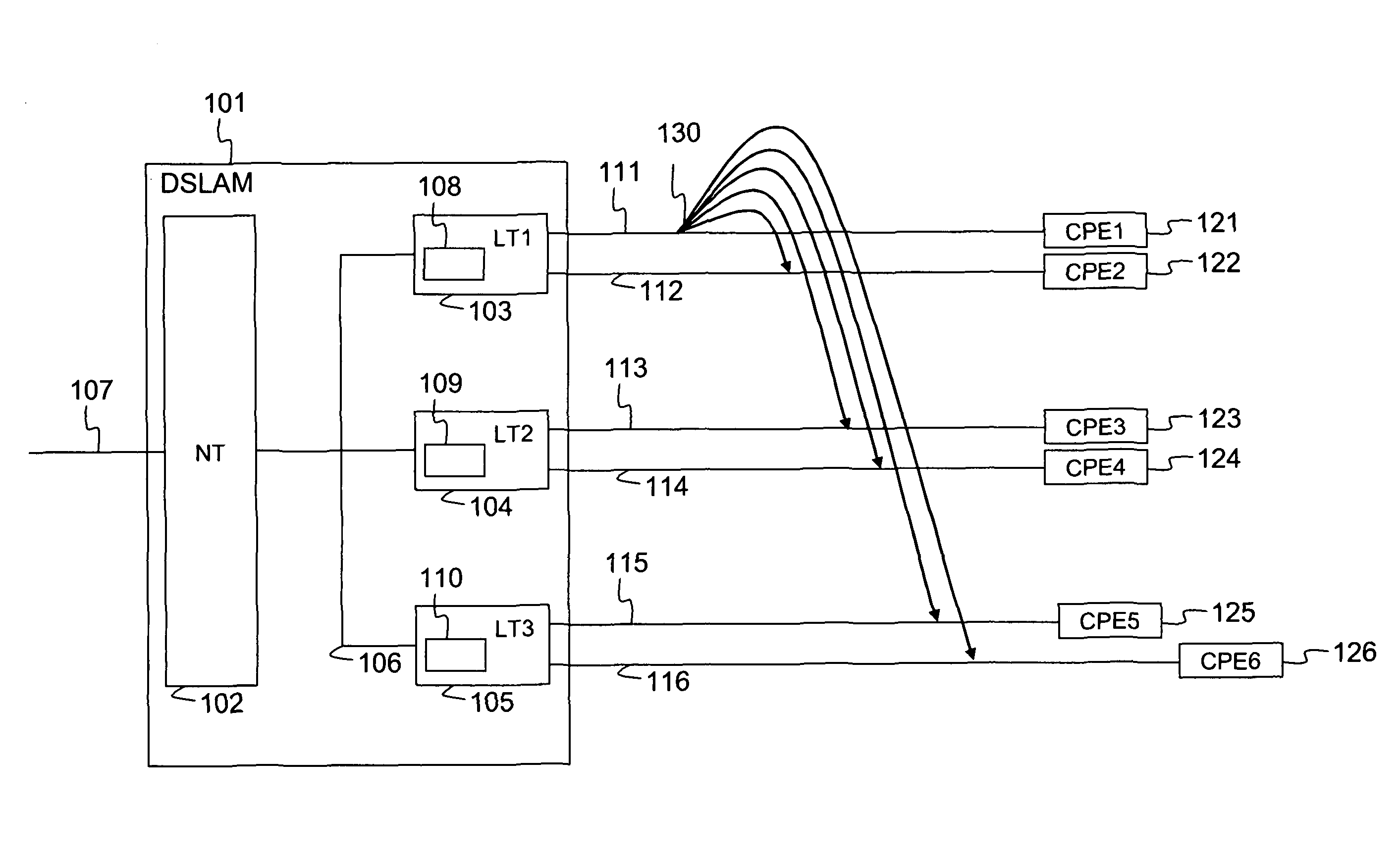
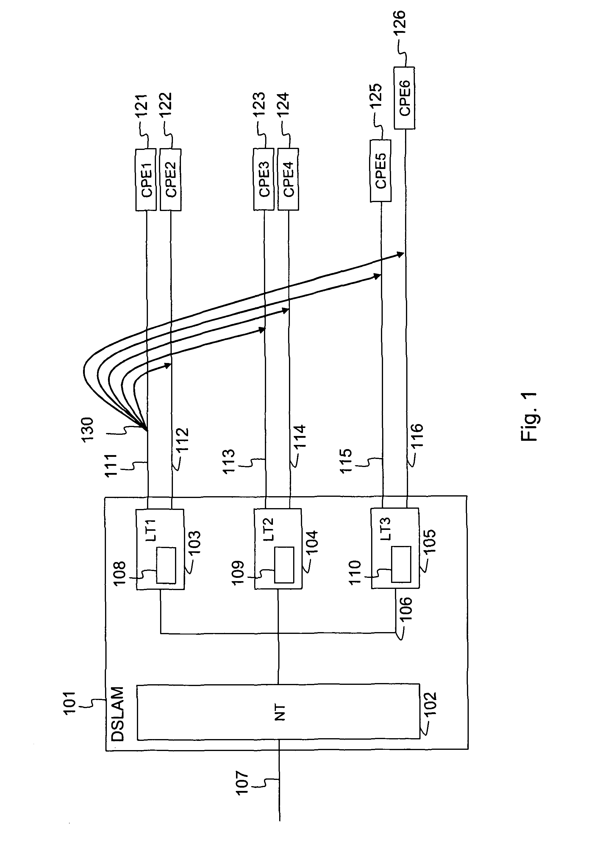
[0033]FIG. 1 illustrates an overview of a DSL network with a Digital Subscriber Line Access Multiplexer (DSLAM) 101 and multiple pieces of Customer Premises Equipment (CPE) CPE1 to CPE6, respectively numbered 121 to 126. The DSLAM 101 is made up out of a network termination (NT) 102, line termination boards (LT) LT1 to LT3, respectively numbered 103 to 105. Each line termination board 103 to 105 is connected to two subscriber lines 111 to 116, which are in turn connected to CPE1 to CPE6. Each LT 103 to 105 is further connected to the network termination 102 by means of a bus 106. The network termination 102 is also connected to an upstream link 107 which connects DSLAM 101 with the edge network or aggregation network of the DSL operator whereto DSLAM 101 belongs.

[0034]Each LT 103 to 105 is provided with an embodiment of the device according to the present invention 108 to 110 to measure crosstalk between multiple subscriber lines. For instance, in this particular example, LT1103 is...


PUM


Abstract

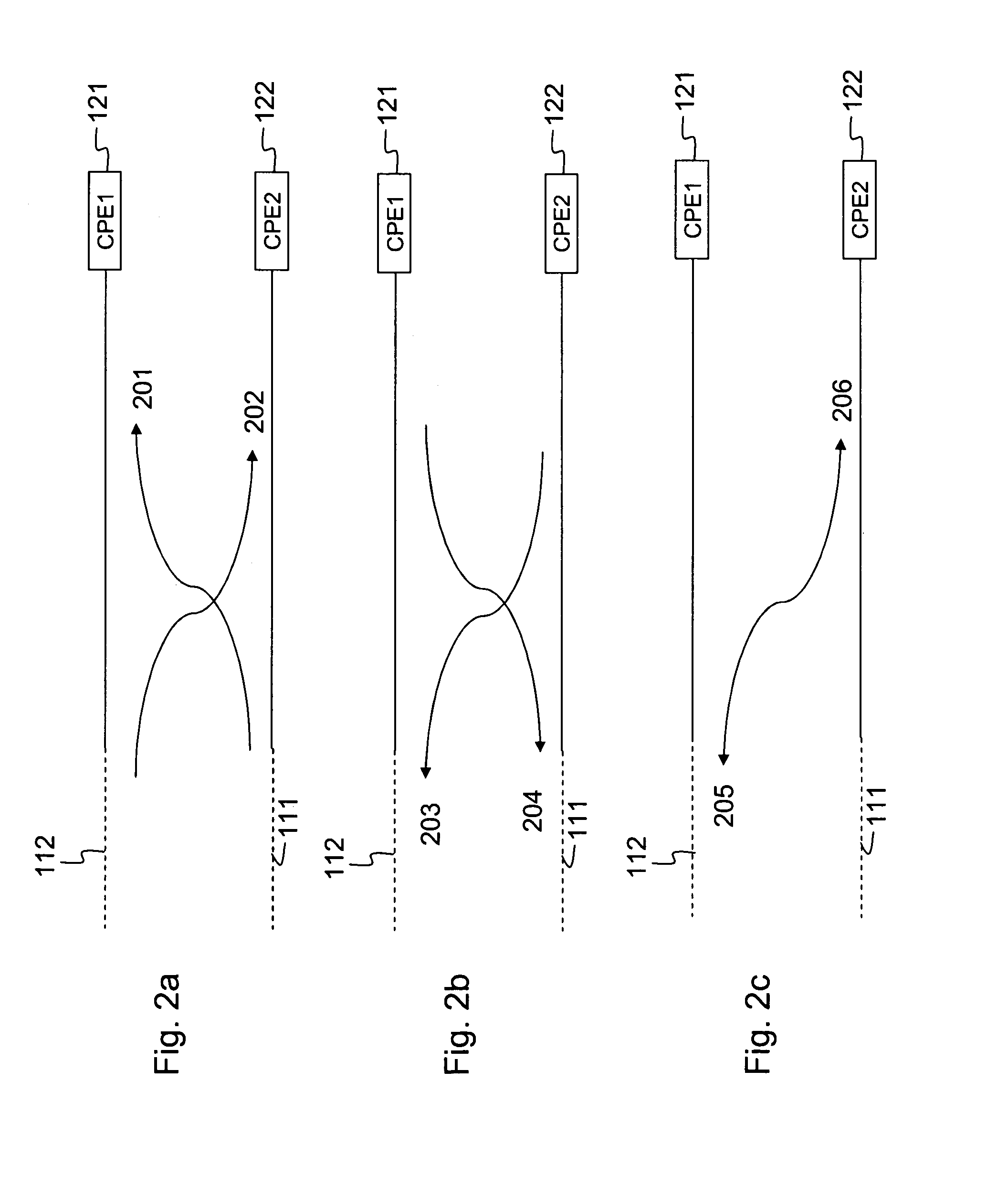
The present invention relates to a device (108, 109, 110) comprising an interface to at least one active subscriber line (112) and an interface to at least one inactive subscriber line (111). The device (108, 109, 110) comprises means for transmitting a first signal on the inactive subscriber line (111) and means for synchronously measuring crosstalk (130; 201, 203, 205, 207) induced into the active subscriber line (112) by transmitting the first signal on the inactive subscriber line (111).

Description

FIELD OF THE INVENTION[0001]The present invention generally relates to determining crosstalk into active communication lines and more in particular to determining crosstalk between subscriber lines in scenario's where an upcoming subscriber line is involved.BACKGROUND OF THE INVENTION[0002]Transmission of data at high speeds, for instance in Asymmetric Digital Subscriber Line (ADSL) or Very high-speed Digital Subscriber Line (VDSL) networks, commonly referred to as xDSL networks is subject to errors injected by external sources. One particular problem is the influence of crosstalk between various subscriber lines within close vicinity. Crosstalk is the effect whereby a first subscriber line induces signals on a second, different subscriber line which act as noise on that second subscriber line. Such effects are especially noticed when multiple subscriber lines form part of the same cable or cable binder or when they are terminated close to each other, for instance in a Digital Subsc...

Claims


Application Information

Patent Timeline
Patent Type & Authority Patents(United States)
IPC IPC(8): H04M3/30
CPCH04B3/487
Inventor GUENACH, MAMOUNMAES, JOCHENPEETERS, MICHAELVERLINDEN, JAN SYLVIA
Owner RPX CORP
Learn More