
MEMS microphone

a microphone and membrane technology, applied in the field ofmems microphones, can solve the problems of low mechanical stability, high susceptibility of membrane, and the miniaturization of mems microphones, and achieve the effect of avoiding contamination or damage to the membrane of the microphon

Active Publication Date: 2013-10-29
TDK CORPARATION
View PDF14 Cites 13 Cited by
  • Summary
  • Abstract
  • Description
  • Claims
  • Application Information

AI Technical Summary

Benefits of technology

The patent text describes a way to protect a MEMS microphone from damage and contamination. This is done by incorporating the microphone into a housing with a sound opening and an angled sound channel that guides the sound to the microphone without contaminating it. The angled sound channel can be achieved by offsetting the sound opening and microphone membrane or chip, tilting the chip, or leading the sound channel around the chip. The technical effect of this is that it creates a safer and less vulnerable MEMS microphone that can withstand many different environments and conditions.

Problems solved by technology

What is disadvantageous about miniaturized MEMS microphones is, in particular, their low mechanical stability, since the microphone membrane has a high susceptibility to fracture by virtue of the small material thickness.
Moreover, during speech transmission at relatively high frequencies, a nonlinear frequency response with resonant magnifications is observed with these microphones, which is undesirable in acoustics and in particular in the case of microphones and impairs the transmission quality.
As a result of the miniaturization, furthermore, the distance between sound entry opening and membrane is shortened, such that the membrane is more susceptible to contaminants which can deposit on the membrane, which in turn cause to an increased extent nonlinearities and resonant magnifications during transmission, impair the functionality of the membrane or even damage the membrane.

Method used


Image

  • MEMS microphone
  • MEMS microphone
  • MEMS microphone

Examples


Embodiment Construction

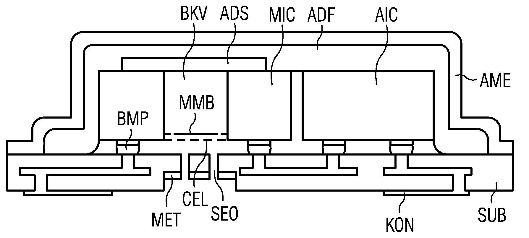
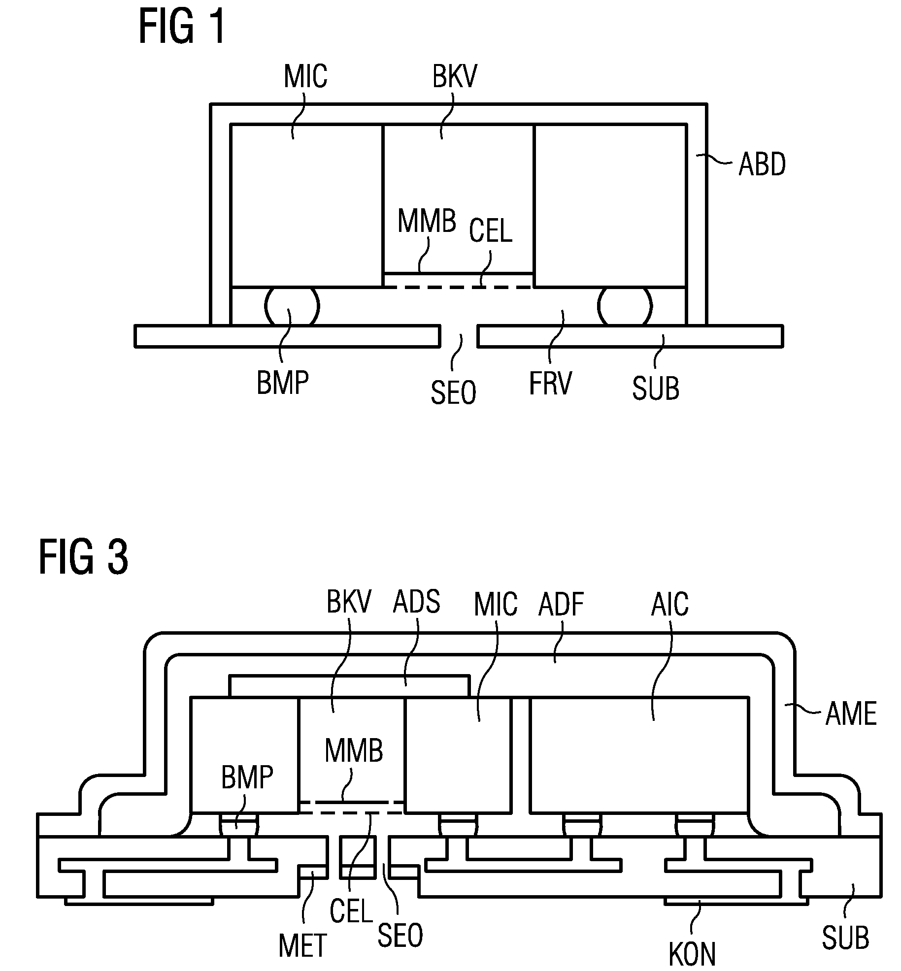
[0042]FIG. 1 shows the simplest possible construction of a microphone package according to the invention on the basis of a schematic cross section. The microphone chip MIC is embodied as an MEMS component composed of a crystalline material, in particular composed of crystalline silicon. With the aid of its downwardly facing contacts, it is mounted on a substrate SUB by means of bumps BMP and is also electrically contact-connected via the bumps.

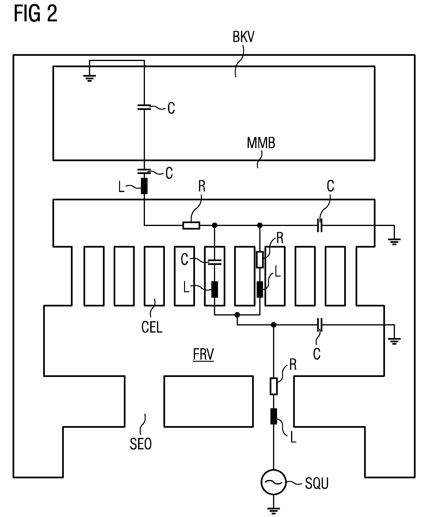
[0043]The microchip MIC operates, for example, according to the capacitive principle and, for this purpose, has a membrane MMB at a small distance from a rigid counterelectrode CEL, which are both arranged at the downwardly facing surface of the microphone chip. Above / behind the membrane there is a cutout BKV, which is produced for the purpose of exposing the membrane, for example by means of etching from the top side. Arranged below / in front of the membrane, but with a reduced cross section with respect to the membrane area, there is a sound ...


PUM


Abstract

A microphone package wherein an MEMS microphone chip (MIC) is mounted on a substrate (SUB) and is sealed with a cover (ABD) with respect to the substrate. The membrane (MMB) of the microphone chip is connected to a sound entry opening (SEO) in the substrate via an acoustic channel. As a result of defined dimensioning of, in particular, the cross section and length of sound entry opening and channel, an acoustic low-pass filter is formed, the −3 dB attenuation point of which is significantly below the natural resonance of microphone membrane and package.

Description

CROSS-REFERENCE TO RELATED APPLICATION[0001]This application is a continuation of prior International Patent Application Serial No. PCT / EP2010 / 053718, filed Mar. 22, 2010, entitled “Mems Microphone,” which claims the benefit of priority of Germany Patent Application Serial No. 10 2009 019 446.0, filed in Germany on Apr. 29, 2009, each of which is hereby incorporated by reference.COPYRIGHT[0002]A portion of the disclosure of this patent document contains material which is subject to copyright protection. The copyright owner has no objection to the facsimile reproduction by anyone of the patent disclosure, as it appears in the Patent and Trademark Office patent files or records, but otherwise reserves all copyright rights whatsoever.BACKGROUND OF THE INVENTION[0003]Miniaturized microphones are nowadays increasingly being produced as MEMS microphones (=microelectro-mechanical system) with the aid of micromechanical structuring technology from a crystalline material, in particular a sem...

Claims


Application Information

Patent Timeline
Patent Type & Authority Patents(United States)
IPC IPC(8): H04R25/00H04R9/08
CPCH04R1/2884H04R19/005H01L24/97H01L2224/16225H01L2924/1461H01L2924/00H01L2924/14H01L2924/00014H01L2924/00011H01L2224/0401H04R1/28H04R19/00
Inventor FEIERTAG, GREGORLEIDL, ANTONPAHL, WOLFGANGWINTER, MATTHIASSIEGEL, CHRISTIAN
Owner TDK CORPARATION
Learn More