Compressor stator vane

a compressor and stator technology, applied in the field of compressor components, can solve problems such as cracking or failure of compressor components, and achieve the effect of minimal impact on blade aerodynamics and efficiency, and natural frequency of airfoil

Active Publication Date: 2013-11-05
ANSALDO ENERGIA SWITZERLAND AG
View PDF22 Cites 56 Cited by
  • Summary
  • Abstract
  • Description
  • Claims
  • Application Information

AI Technical Summary

Benefits of technology

[0006]In accordance with the present invention, there is provided a novel and improved compressor component having a non-linear airfoil thickness that results in an altered natural frequency of the airfoil. The location of the airfoil thickness has been modified at a distance along the airfoil span so as to shift the natural frequency of the blade with minimal impact to blade aerodynamics and efficiency.

Problems solved by technology

When the natural frequency of the compressor component coincides or crosses an engine order, the compressor component can start to resonate or vibrate in such away that it is excited and can cause cracking or failure of the compressor component.

Method used


Image

  • Compressor stator vane
  • Compressor stator vane
  • Compressor stator vane

Examples


Embodiment Construction

[0019]The subject matter of the present invention is described with specificity herein to meet statutory requirements. However, the description itself is not intended to limit the scope of this patent. Rather, the inventors have contemplated that the claimed subject matter might also be embodied in other ways, to include different components, combinations of components, steps, or combinations of steps similar to the ones described in this document, in conjunction with other present or future technologies.

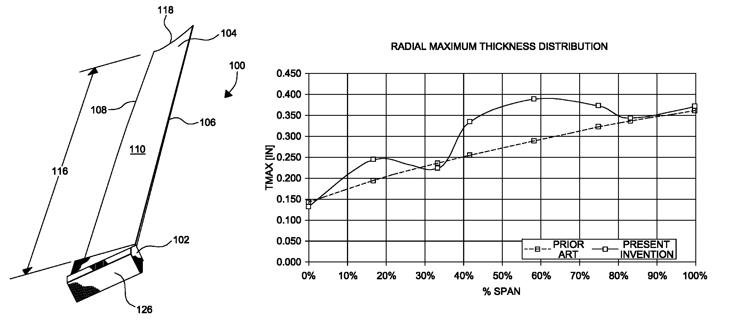
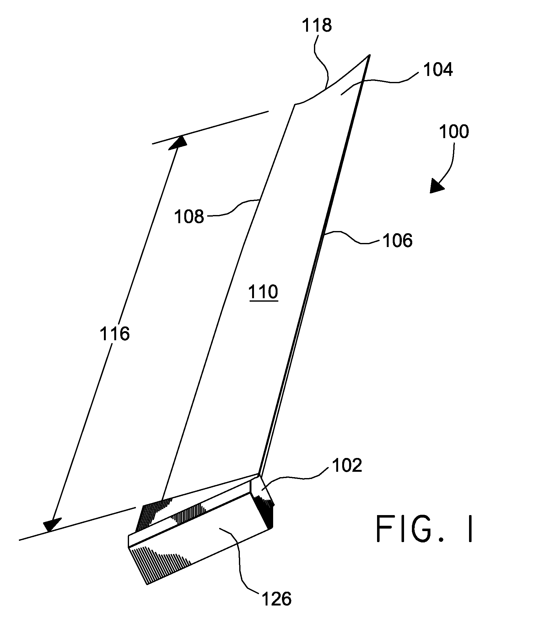
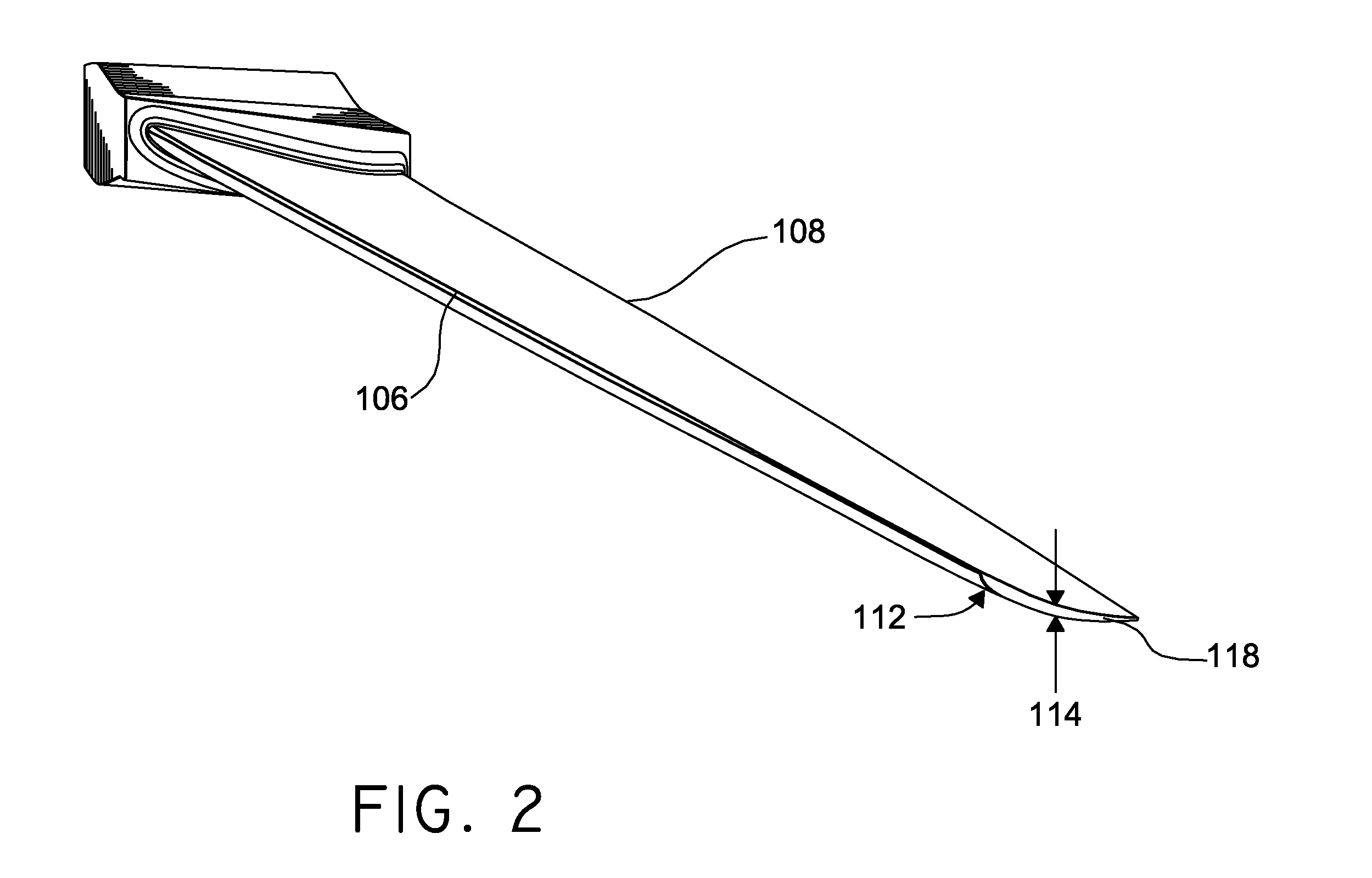
[0020]Referring initially to FIGS. 1 and 2, a compressor component 100, such as a stator vane, is shown in accordance with an embodiment of the present invention. The compressor component comprises an attachment 102 and an airfoil 104 extending radially outward from the attachment 102. The airfoil 104, which can be solid or alternatively hollow, has a leading edge 106 and a trailing edge 108 spaced a distance from the leading edge 106. The airfoil 104 also has a concave surface 110 ...


PUM


Abstract

A compressor component having a non-linear thickness distribution along the span length is disclosed. By altering the thickness distribution to a non-linear arrangement so as to locally increase airfoil thickness proximate a mid-span location, the natural frequency of the airfoil is increased so as to not coincide with a critical engine order of the compressor. Further, the present invention provides a novel airfoil profile in accordance with the coordinates of Table 1. The present invention also includes a carrier segment or disk fabricated from a material so as to eliminate corrosion with the compressor component.

Description

CROSS-REFERENCE TO RELATED APPLICATIONS[0001]Not applicable.TECHNICAL FIELD[0002]The present invention generally relates to a compressor component having an airfoil and more specifically to an improved airfoil profile that has a variable thickness along the airfoil span in order to raise the natural frequency of the compressor component and minimize excitation of the component.BACKGROUND OF THE INVENTION[0003]A compressor typically comprises a plurality of stages, where each stage includes a set of stationary compressor vanes which direct a flow of air into a rotating disk of compressor blades, where each stage of the compressor decreases in diameter, causing the pressure and temperature of the air to increase. Compressor components having an airfoil, such as compressor blades and compressor vanes, are held within disks or carriers and are designed to aid in compressing a fluid, such as air, as it passes through stages of blades and vanes of the compressor.[0004]Axial compressors ha...

Claims


Application Information

Patent Timeline
Patent Type & Authority Patents(United States)
IPC IPC(8): F01D5/14
CPCF01D5/141F04D29/542F04D29/668F04D29/544
Inventor WANG, YONGSTROHL, JAMES PAGE
Owner ANSALDO ENERGIA SWITZERLAND AG
Why Eureka
Try Eureka