Busbar

a busbar and a technology of a busbar body, applied in the field of busbars, can solve the problems of large number of components, time-consuming process of assembling, and troublesome assembling process, so as to improve the working property of assembling, reduce the number of components, and reduce the time of assembling

Active Publication Date: 2013-11-05
YAZAKI CORP
View PDF16 Cites 5 Cited by
  • Summary
  • Abstract
  • Description
  • Claims
  • Application Information

AI Technical Summary

Benefits of technology

[0019]According to the present invention claimed in claim 1, the circuit body is connected directly to the busbar, so that an additional component connected with the circuit body and joining to the busbar is not required. Therefore, number of components can be reduced. The terminal is not required, so that number of steps of processes can be educed and time of assembling can be shortened and working property of assembling can be improved.
[0020]According to the present invention claimed in claim 2, the cross-sectional area of the bridge portion is configured to be smaller than the cross-section area of the welding portion, so that when welding the busbar and the circuit body, heat generated at the welding portion is not easily flowed through the bridge portion to the battery connecting portion. Thereby, the conductive core wire can be welded with the welding portion efficiently, so that the busbar and the circuit body can be welded securely.
[0021]According to the present invention claimed in claim 3, by overlapping the conductive core wire on the projection projecting from the surface of the welding portion and welding them, an area of a contact point of the welding portion and the conductive core wire can be reduced. Thereby, when the busbar and the circuit body are welded, construction resistance is formed at the contact point so that heat by resistance can be easily generated and the generated heat is not easily flowed to the bridge portion. Therefore, the welding portion and the conductive core wire can be melted efficiently and the busbar and the circuit body can be securely welded to each other.
[0022]According to the present invention claimed in claim 4, the plurality of plate portions overlapped to each other can be easily bent more than one plate portion having a thickness equal to total of each thickness of the plurality of plate portions. Thereby, when the batteries have dispersion about a height of the electrodes thereof, the plurality of plate portions can be bent so as to absorb the dispersion. Therefore, the busbar and the electrode of the battery can be securely connected. The busbar can be formed by pressing thinner metal sheet, so that the busbar can be manufactured with good yield and manufacturing cost can be reduced.

Problems solved by technology

The busbar 101 and the voltage detecting terminal 109 are separated component to each other, so that there is a problem that number of components becomes large.
Furthermore, it is required that both of the busbar 101 and the voltage detecting terminal 109 is mounted at the busbar receiving section 152, so that process of assembling becomes troublesome and the process of assembling requires much time.

Method used


Image

  • Busbar
  • Busbar
  • Busbar

Examples


Embodiment Construction

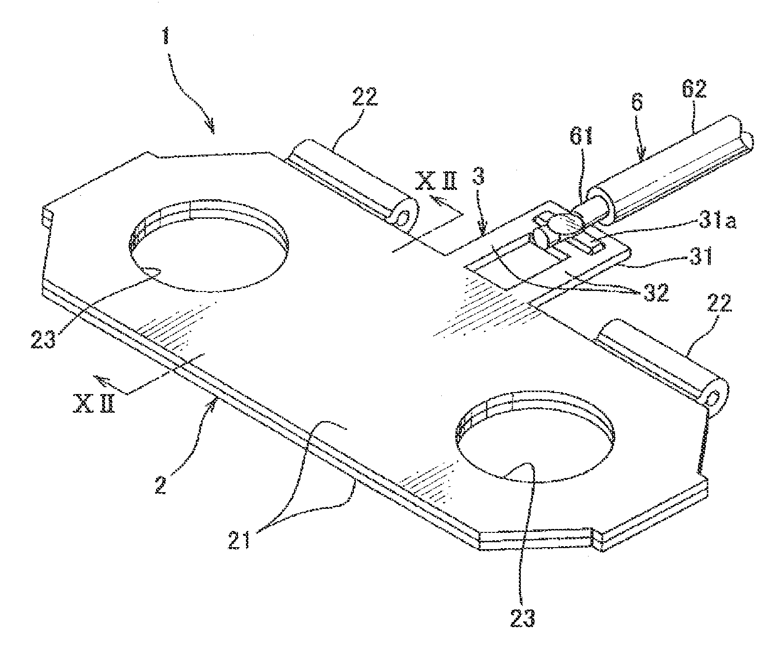
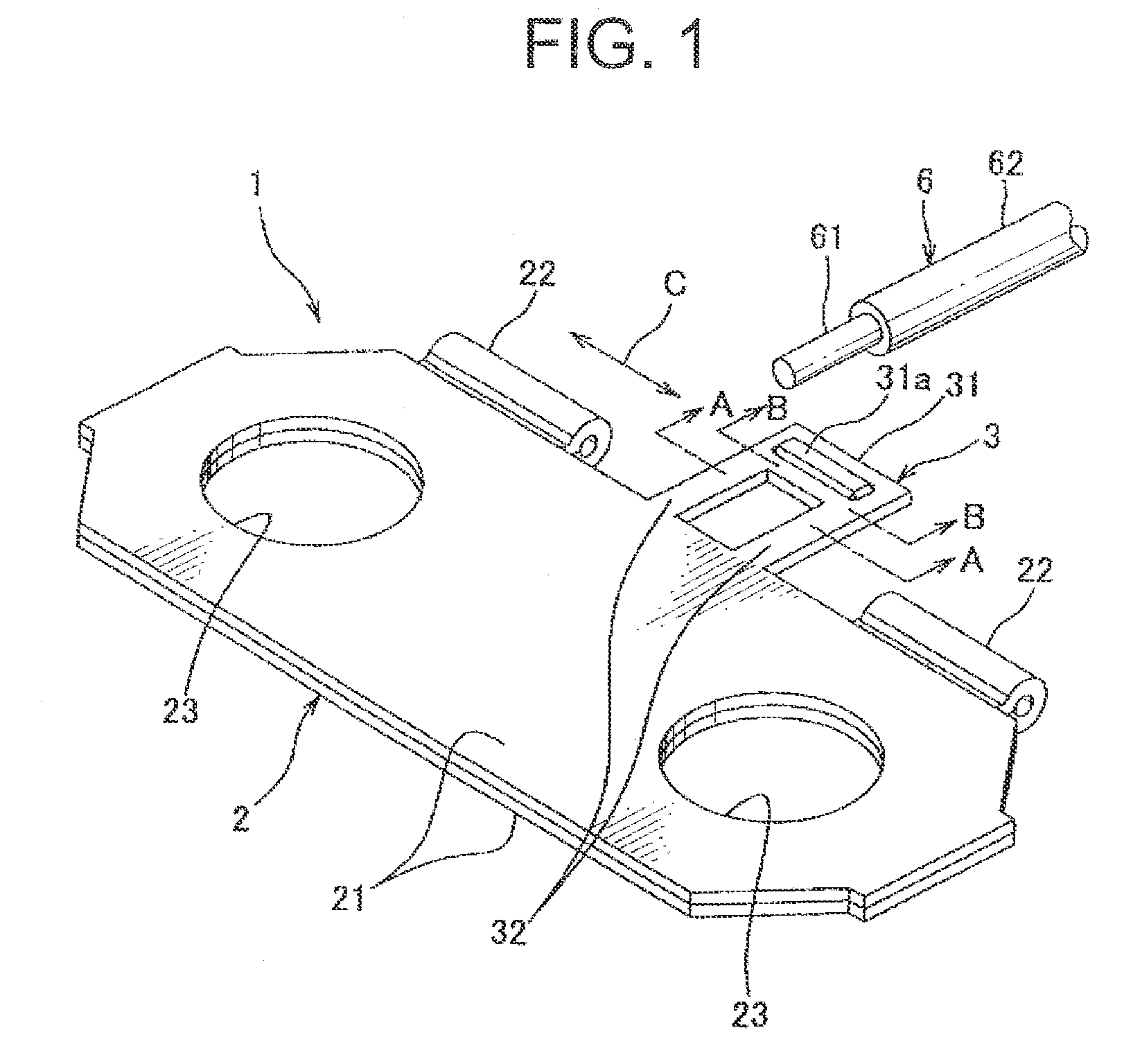
[0038]A busbar of one embodiment according to the present invention will be described with reference to drawings FIGS. 1-12. The busbar 1 of the one embodiment according to the present invention shown in FIG. 1 structures an electric power supply 10 shown in FIG. 2. The electric power supply 10 is mounted at an electric car driven by an electric motor and a hybrid car driven by both an electric motor and an engine, and supplies electric power to the electric motor.

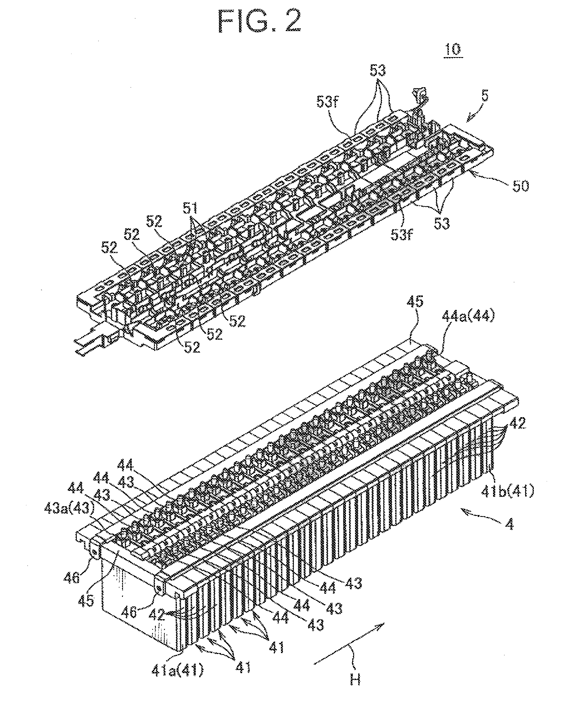
[0039]The electric power supply 10 includes a battery assembly 42 and a busbar module 5 as shown in FIG. 2. The battery assembly 4 includes a plurality of batteries 41, an end plate 45 and a fixing band 46.

[0040]The battery 41 includes a battery main body 42, a positive electrode 43 and a negative electrode 44. The battery main body 42 is formed into a flat box shape. The positive electrode 43 and the negative electrode 44 are formed into a rod shape projecting upwardly from a top surface located at a top side in FIG. 2 of...


PUM

PropertyMeasurementUnit
conductiveaaaaaaaaaa
areaaaaaaaaaaa
voltageaaaaaaaaaa

Abstract

A busbar includes a battery connecting portion and a wire connecting portion as a circuit body connecting portion. The battery connecting portion connects electrodes of two batteries to each other. The wire connecting portion is continued to the battery connecting portion, and connected directly with an electric wire so as to overlap a core wire of an electric wire thereon. The wire connecting portion includes a welding portion which the core wire of the electric wire is welded to, and a bridge portion connecting the welding portion and the battery connecting portion. A cross-sectional area of the bridge portion along an intersecting direction intersecting a direction of connecting the welding portion and the battery connecting portion is formed to be smaller than a cross-sectional area of the welding portion along the intersecting direction.

Description

CROSS REFERENCE TO RELATED APPLICATIONS[0001]This application is a National Stage of International Application No. PCT / JP2010 / 061881 filed Jul. 14, 2010, claiming priority based on Japanese Patent Application No. 2009-188833 filed Aug. 18, 2009, the contents of all of which are incorporated herein by reference in their entirety.TECHNICAL FIELD[0002]This invention relates to a busbar applied to an electric power supply including a plurality of batteries and connecting electrodes of two batteries to each other.BACKGROUND ART[0003]An electric car driven by an electric motor and a hybrid car driven by both an electric motor and an engine require an electric power supplying high-voltage electric power to the electric motor for smooth driving. An electric power supply structured by connecting a plurality of relatively small batteries in series (see Patent Document 1) is mounted in the electric car and the hybrid car.[0004]FIG. 13 is a plan view of an electric power supply by prior art. Th...

Claims


Application Information

Patent Timeline
Patent Type & Authority Patents(United States)
IPC IPC(8): H01R3/00H01M50/505H01M50/507H01M50/51
CPCH01M2/206H01M10/425H01M10/482H01M2220/20Y02E60/10H01M50/51H01M50/507H01M50/505
Inventor IKEDA, TOMOHIROYANAGIHARA, SHINICHIINOUE, HIDEKI
Owner YAZAKI CORP
Why Eureka
Try Eureka