Heat exchanger-integrated reaction device having supplying and return ducts for reaction section

a technology of reaction device and heat exchanger, which is applied in the direction of gas-gas reaction process, heating type, separation process, etc., can solve the problems of high energy-saving reaction device with high heat recovery performance, large heat dissipation rate at device elements and piping connecting them, etc., to achieve the effect of saving heating energy for reaction, reducing the number of reaction devices, and controlling the selectivity of reaction highly accurately

Inactive Publication Date: 2013-11-05
NAT INST OF ADVANCED IND SCI & TECH
View PDF9 Cites 1 Cited by
  • Summary
  • Abstract
  • Description
  • Claims
  • Application Information

AI Technical Summary

Benefits of technology

[0031]According to the present invention, a desired reaction speed can be obtained by preheating a fluid to be reacted thoroughly, or the temperature of the reaction section can be stabilized to control the selectivity of reaction highly accurately, thus improving the performance of the reaction device dramatically. In addition, heating energy necessary for reaction can be saved. Furthermore, even if the outlet of the supplying path of the heat exchange section is divided into many regions to enhance heat recovery performance, the quantity of reaction element such as honeycomb catalyst can be reduced to one or two if the ducts of the reaction section are integrated into one for each of the supplying and return paths, which minimizes the time and trouble of replacing degraded reaction elements. In addition, when heating the reaction elements and the fluid on the supplying / return paths within this device, that objective can be achieved by placing a heating element at only one position because the reaction section is in a consecutive flow path structure. Even when the ducts in the reaction section are not integrated into one for each of the supplying and return paths, the number of heating elements can be reduced by the number of ducts of the reaction section reduced, compared with the conventional art wherein integration is not performed at all. Consequently, the device remains simple. The present invention is ideal as a small and high-performance reaction device for removing toxic components in gas. In particular, it is suitable for purifying air containing VOC in low concentrations and low-temperature exhaust gas from automobiles.

Problems solved by technology

However, since a small device must be used to detoxify gases having the treatment flow of 10 m3 / min or lower, heat dissipation rate at device elements and piping connecting them becomes relatively large.
In addition, since a heat exchanger that is compact but has high heat recovery performance and high heat resistance cannot be obtained, a highly energy-saving reaction device having high heat recovery performance has yet to be commercialized.

Method used


Image

  • Heat exchanger-integrated reaction device having supplying and return ducts for reaction section
  • Heat exchanger-integrated reaction device having supplying and return ducts for reaction section
  • Heat exchanger-integrated reaction device having supplying and return ducts for reaction section

Examples


example

[0065]Heat recovery performance test by catalytic combustion of low-concentration hydrogen)

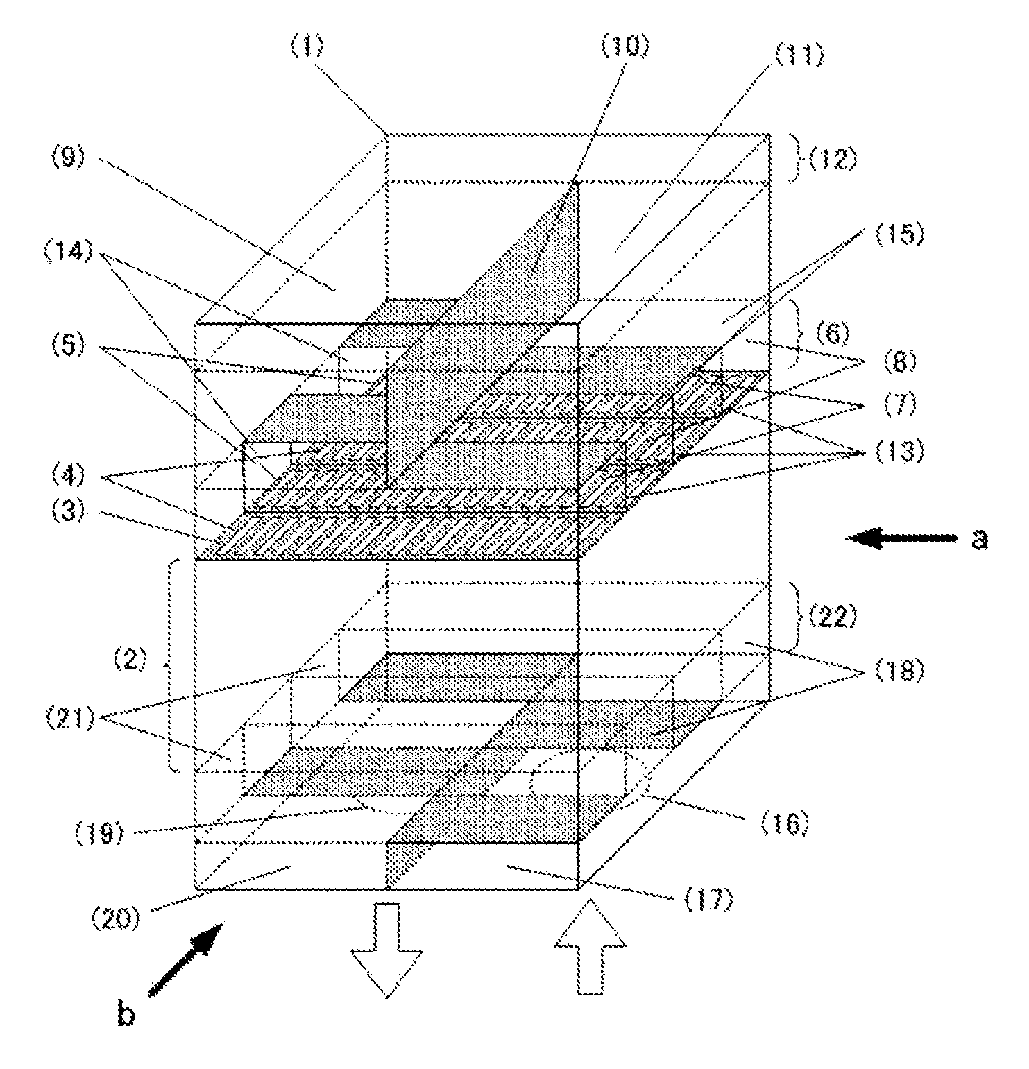
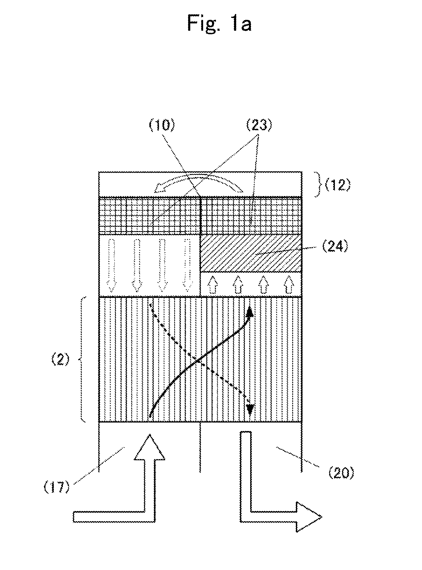
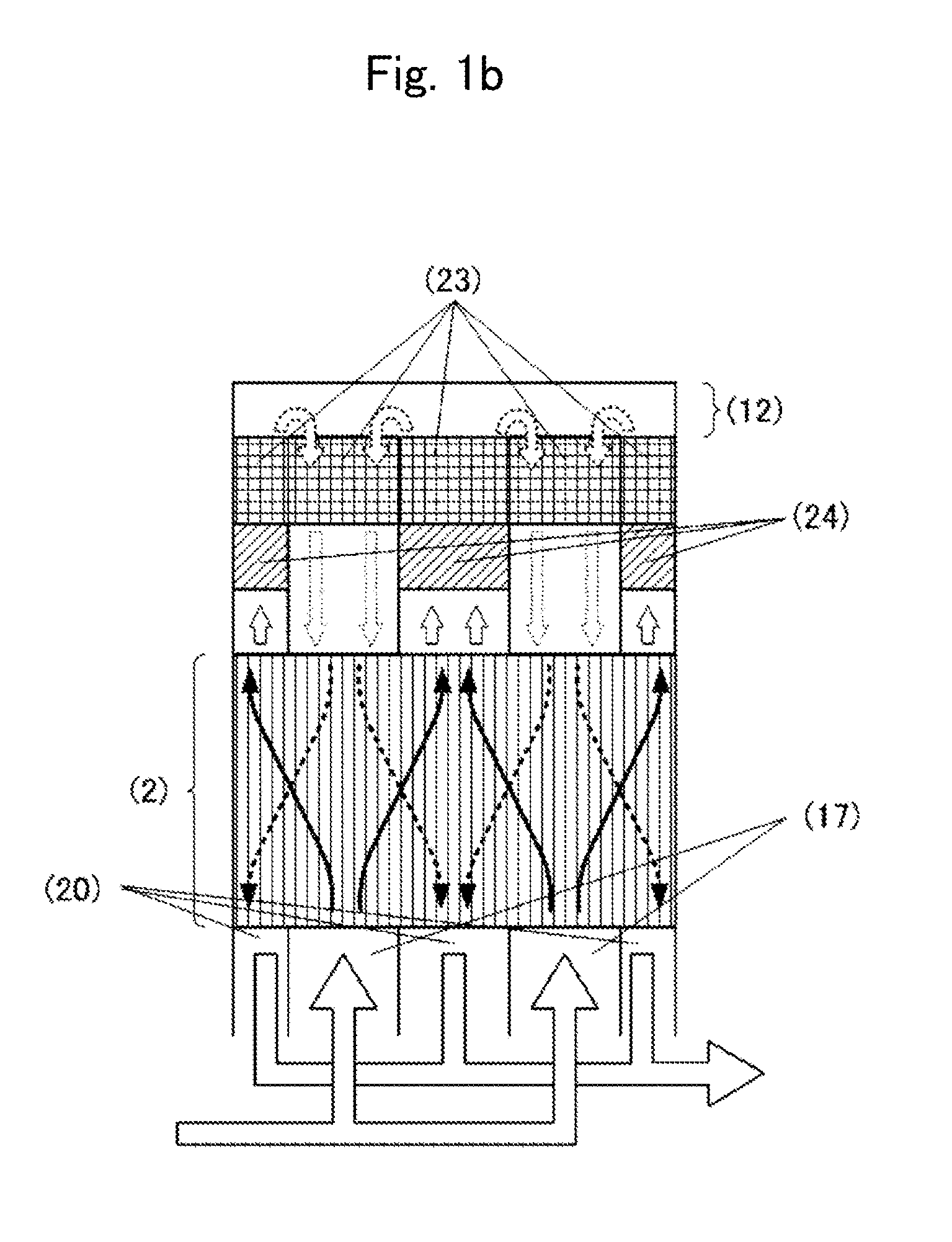
[0066]To confirm the effect of the present invention, a heat exchanger-integrated reaction device as shown in FIG. 8, whose side surface 3 is in the form of six ridges having cross section in the shape of an isosceles right triangle and which has two supplying ducts and one return duct, was created experimentally. FIG. 9 is a cross-sectional view of the central portion around the heat exchange section of the prototype reaction device. The heat exchange section measures approximately 180 mm in width, 130 mm in total length in the flow direction, 180 mm in the thickness in stacking direction, and 2.0 mm in the distance between each flow in the gap. As shown by the flow lines drawn in the figure, the supplying and return flows within the heat exchange section is made to be fairly close to a perfect counter flow thanks to the inlet / outlet region of the heat exchange section divided into many secti...


PUM


Abstract

A compact heat exchanger-integrated reaction device, comprising a heat exchange section and a reaction section, capable of providing high heat recovery performance, with a small number of ducts of the reaction section formed for supplying and return paths without increasing the volume of the entire reaction device. With the heat exchanger-integrated reaction device equipped with ducts in the reaction section adjacent to the plate-stacking-type heat exchange section, collection ducts for allowing a plurality of regions having openings for discharging a fluid to be processed to be connected with at least one supplying duct of the reaction section, and distribution ducts for allowing at least one supplying duct of the reaction section to be connected with a plurality of regions having openings for receiving the fluid from the heat exchange section are provided between the heat exchange section and the duct of the reaction section.

Description

TECHNICAL FIELD[0001]The present invention relates to a reaction device equipped with both self-heat-exchange function and reaction function, more specifically, a reaction device capable of reducing heating energy necessary for reactions, or increasing and stabilizing the temperature of a reaction section, thus allowing a desired reaction to progress highly efficiently, by recovering the heat generated in the reaction section with the heat exchanger and efficiently preheating a fluid before reaction.BACKGROUND ART[0002]To cause chemical reactions, to detoxify toxic components contained in a fluid by decomposition or oxidation, in particular, the fluid to be treated is heated to increase the speed of desired chemical reaction. Furthermore, in order to perform the heating efficiently, the heat recovered from treated high-temperature fluid is fed to low-temperature fluid that is to be treated to preheat the low-temperature fluid. This procedure has been put to practical use as relative...

Claims


Application Information

Patent Timeline
Patent Type & Authority Patents(United States)
IPC IPC(8): B01J19/00F28F3/00F28F3/08
CPCB01D53/8668F24F12/006B01D2257/708Y02B30/563F28D2021/0022F28F9/026F28D9/00Y02B30/56
Inventor OBUCHI, AKIRAUCHISAWA, JUNKONAMBA, TETSUYAOOI, AKIHIKOIIJIMA, NORIO
Owner NAT INST OF ADVANCED IND SCI & TECH
Why Eureka
Try Eureka