

Drill
a drill and drill bit technology, applied in the field of drills, can solve the problems of low research or development of drills used for devices requiring operator's power to drill holes, problems such as drilling holes, and manufacturers of drills have spent little time on research for reducing high drilling resistance, so as to reduce drilling resistance and improve drilling accuracy. , the effect of reducing the drilling resistan
Active Publication Date: 2013-11-12
BIC TOOL
View PDF22 Cites 9 Cited by
- Summary
- Abstract
- Description
- Claims
- Application Information
AI Technical Summary
Benefits of technology
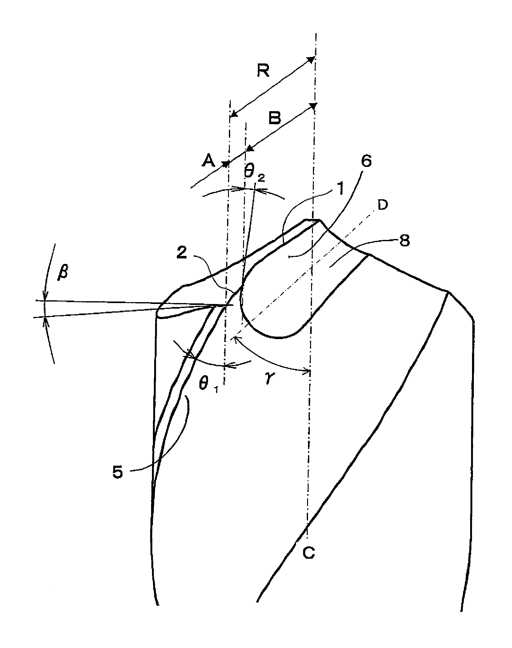
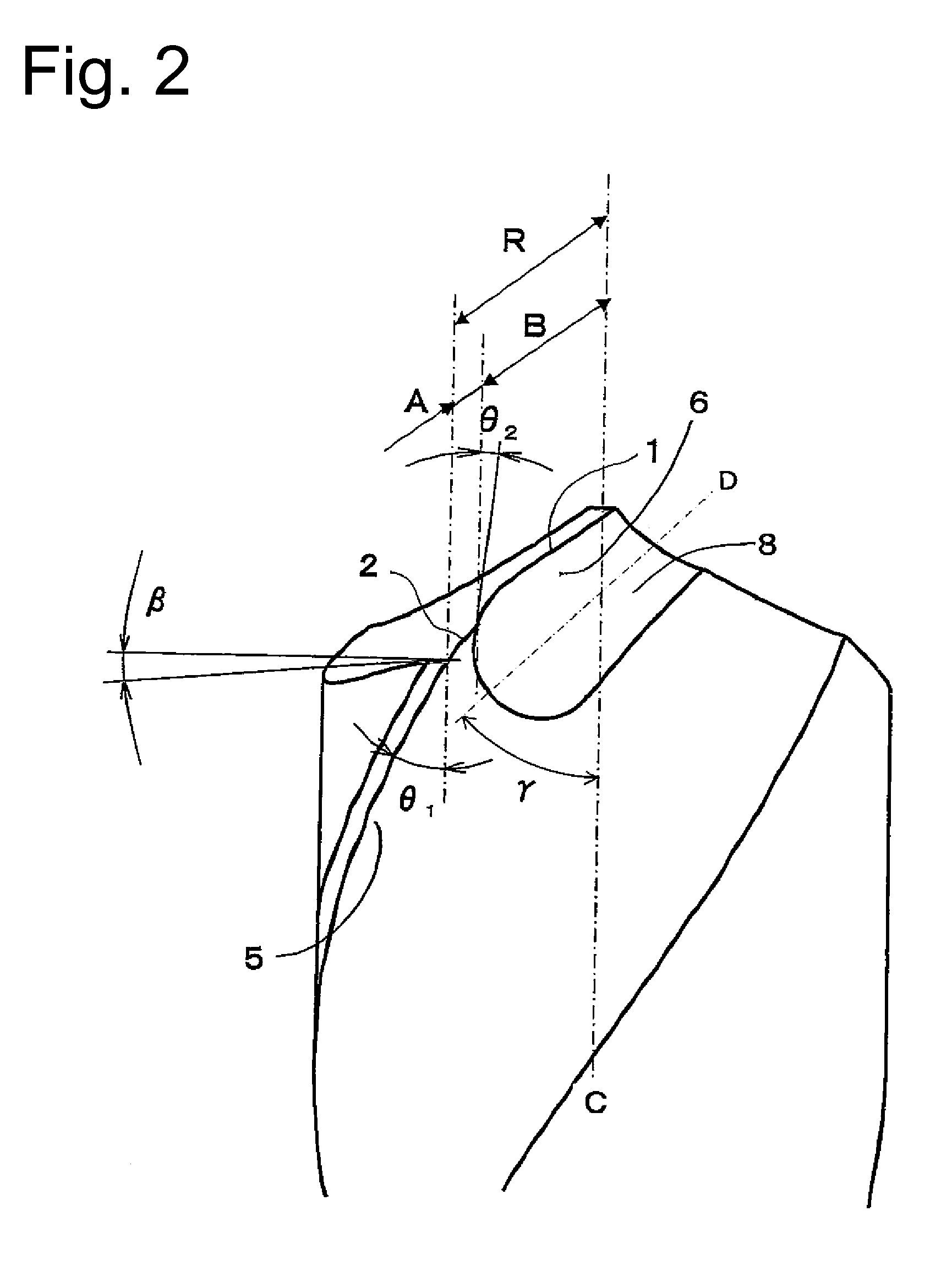
[0021]According to the invention, there is a drill provided which can substantially decrease drilling resistance compared with the conventional drill and can easily drill holes by manpower using a hand drill, a manual drill press, or the like. Moreover, the reduction of drilling resistance improves drilling accuracy and reduces the time to drill holes, leading to improvement of working efficiency. Furthermore, it also allows for significant increase in the drill's life span. Besides, a rake angle θ1 formed by the main cutting blade and a rake angle θ2 formed by the thinning cutting blade satisfy θ1>θ2, except for a part just below the chisel. Therefore, an apparent rake angle becomes smaller and the less portion of the blade edge digs deep into the workpiece, thereby making the cutting blade much easier to drill even if the drill is pressed against the workpiece by manpower such as a hand drill. Moreover, setting θ2>0° prevents any failure as occurred if θ2≦0° is set (as the cutting resistance increases, the sharpness deteriorates).
[0022]Also according to the invention, an extension line extending in a drill tip direction a line along the deepest portion of the thinning surface is offset to heel side or cutting blade side of the drill, without crossing the central part of the drill tip, when seen from front side of the drill. Therefore, a distinct rake part can be formed from chisel to the cutting blade (including a portion of the heel part, too), or from chisel neighborhood, except for just below the chisel, to the cutting blade. This leads to significant improvement of sharpness of the cutting blade.
[0023]Furthermore, according to the invention, the width of the offset is equal to or smaller than 10% of a drill diameter and therefore the drilling resistance can be more surely decreased, which drastically improves high efficiency of the cutting blade.
[0024]Additionally, according to the invention, the extension line is offset to the heel side of the drill, and therefore a distinct rake part can be formed from chisel to the cutting blade (including a portion of the heel part, too). This results in a distinct cutting blade from the chisel part to the cutting blade part, and its drilling efficiency significantly improves. Furthermore, the drilling force obtained from the rotation of the drill generates from the moment the drill tip contacts a workpiece (since a rake is also provided at the drill tip, component force for the rake angle generates even by for example rotation of an air drill from the moment the drill contacts the workpiece, and this component force affects the workpiece), and the power which an operator needs to apply on the drill may be smaller. Additionally, the rake angle becomes comparatively larger and the drilling force becomes the largest, compared with the cases where the extension line is offset to the cutting blade side of the drill and where the extension line crosses the central part of the drill tip.
[0025]According to another embodiment of the invention, the extension line is offset to the cutting blade of the drill, and therefore a distinct rake is obtained from the chisel neighborhood to the cutting blade, except for a part just below the chisel. Although there is no rake provided just below the chisel, the chisel width is much narrower than if the extension line is offset to the heel side (case 1), and the chisel width is substantially same as in the case the extension line crosses the central part of the drill tip (case 2). In addition, since a larger thinning part can be formed, drilling resistance can be decreased and the high efficiency equal to or greater than that of the above-described two cases (cases 1 and 2) can be obtained even if no rake is provided just below the chisel.
[0026]Also, according to the invention, the extension line extending in a drill tip direction a line along the deepest portion of the thinning surface crosses the central part of the drill tip, when seen from front side of the drill. Therefore, a distinct cutting blade is shaped from the chisel neighborhood, except for a part just below the chisel, to the cutting blade part and the high drilling efficiency will significantly improve. Since the chisel width is reduced to a minimum, drilling resistance decreases instead and the same drilling force as obtained if the extension line is offset to the heel side, can be obtained.
Problems solved by technology
However, drills used for devices requiring operator's power to drill holes, such as a hand drill or a drill press, have not been positively researched or developed.
Since the drills used for the hand drill and drill press etc drill holes with the use of operator's arm strength, they have problems in drilling holes if drilling resistance is high.
However, manufacturers of drills have spent little time on research for decreasing the high drilling resistance.
Although these drills on which thinning is performed have more effect on reduction of drilling resistance compared to drills on which no thinning is performed (see FIG. 16(c)), they do not have enough resistance reduction effect if they are used for drilling holes with man power using such as a hand drill or a drill press, and thus an operator must withstand heavy strain on his arms.
Therefore, the drilling force of the central part becomes weak, and at the time of drilling with a hand drill, significant power would be required while the drilling by the drill tip from a central part to a peripheral cutting blade has been performed, sinking into the workpiece.
Moreover, a tip tends to chip when used since the chisel width is very narrow, and in particular, a tip of a drill made from powder high-speed steel becomes fragile and more easily chipped.
Therefore, in some cases, drilling resistance may be increased but not decreased by its thinning and thus these drills cannot obtain acceptably high efficiency enough to drill holes taking advantage of manpower, such as a hand drill.
Method used
View moreImage
Smart ImageViewing Examples

Examples
examples
[0080]Hereinafter, the effect of the present invention will be clearer by showing test results on the drill in the examples and comparative examples below according to the present invention. However, the present invention is not limited to the following examples in any way.
[0081]1. A test based on the relation between a length of the main cutting blade (A) and a length of the thinning cutting blade (B)<
Login to View More PUM
| Property | Measurement | Unit |
|---|---|---|
| rake angle | aaaaa | aaaaa |
| helix angle | aaaaa | aaaaa |
| β≦4° | aaaaa | aaaaa |
Abstract
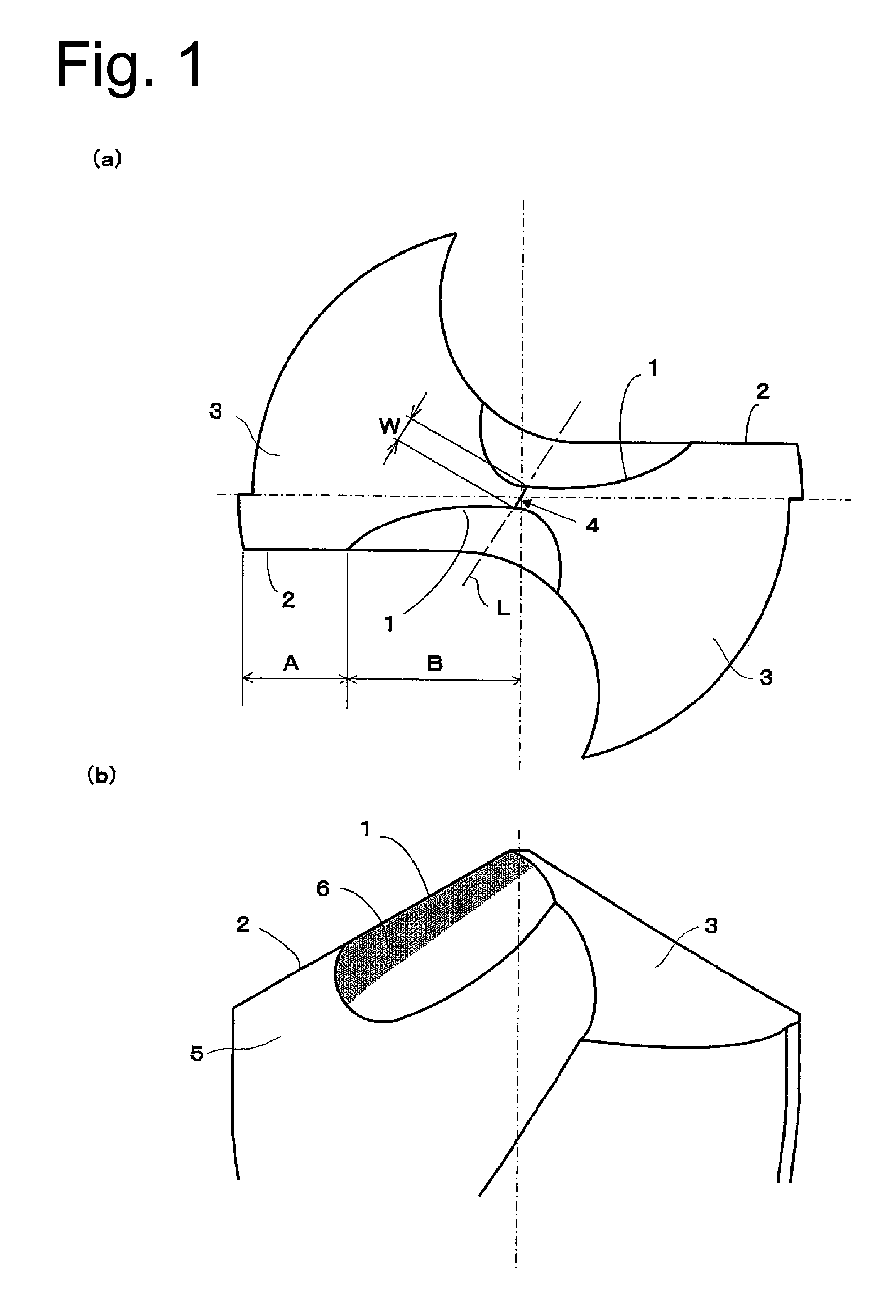
[Problem] To provide a drill which enables a great reduction in cutting resistance and easy performance of a drilling operation by human power using a hand drill, a drilling machine, or the like.[Solution] A drill has two cutting edges formed symmetrically with respect to a rotation axis, and is subjected to thinning at the tip thereof. The cutting edge is configured from a thinned cutting edge (1) which extends in a shape including a curved line from a chisel edge to the outer peripheral side of the drill, and a main cutting edge (2) which extends from the end of the thinned cutting edge to the outer peripheral end of the drill when viewed from the tip side of the drill, and a thinned surface formed by the thinned cutting edge is formed into an approximately parabolic shape inclined in a drill axis direction when viewed from the front side of the drill.
Description
TECHNICAL FIELD[0001]The present invention relates to a drill, in particular, a drill preferably used for drilling holes by manpower using a hand drill, a drill press or the like.BACKGROUND OF THE INVENTION[0002]Recently, among machine tools such as machining centers etc, fully automatic types allowing unmanned processing are becoming the mainstream and thus many kinds of drills corresponding to the fully automatic types have been developed and sold. However, drills used for devices requiring operator's power to drill holes, such as a hand drill or a drill press, have not been positively researched or developed. As a result, drills in almost same configurations have been used over several decades.[0003]Since the drills used for the hand drill and drill press etc drill holes with the use of operator's arm strength, they have problems in drilling holes if drilling resistance is high. However, manufacturers of drills have spent little time on research for decreasing the high drilling r...
Claims
Login to View More Application Information
Patent Timeline
 Patent Type & AuthorityPatents(United States)
IPC IPC(8): B23B51/02
CPCB23B51/02B24B3/32B23B2251/14B23B2251/04Y10T408/9097B23B2251/18Y10T408/9095Y10T408/909B23B2251/085B23B51/00
InventorARAI, KOICHIARAI, GIICHIKIMURA, KATSUYO
OwnerBIC TOOL