
Applicator for microneedle array

a microneedle array and array technology, applied in the field of microneedle arrays, can solve the problems of excessive damage to the skin surface, insufficient absorption of drug-effective components, etc., and achieve the effect of convenient portability

Inactive Publication Date: 2013-11-12
MEDRX CO LTD
View PDF14 Cites 10 Cited by
  • Summary
  • Abstract
  • Description
  • Claims
  • Application Information

AI Technical Summary

Benefits of technology

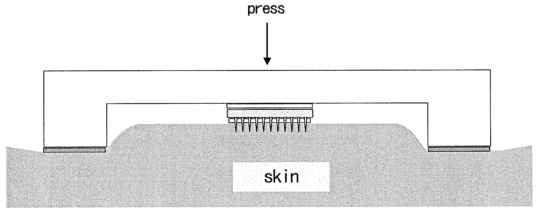
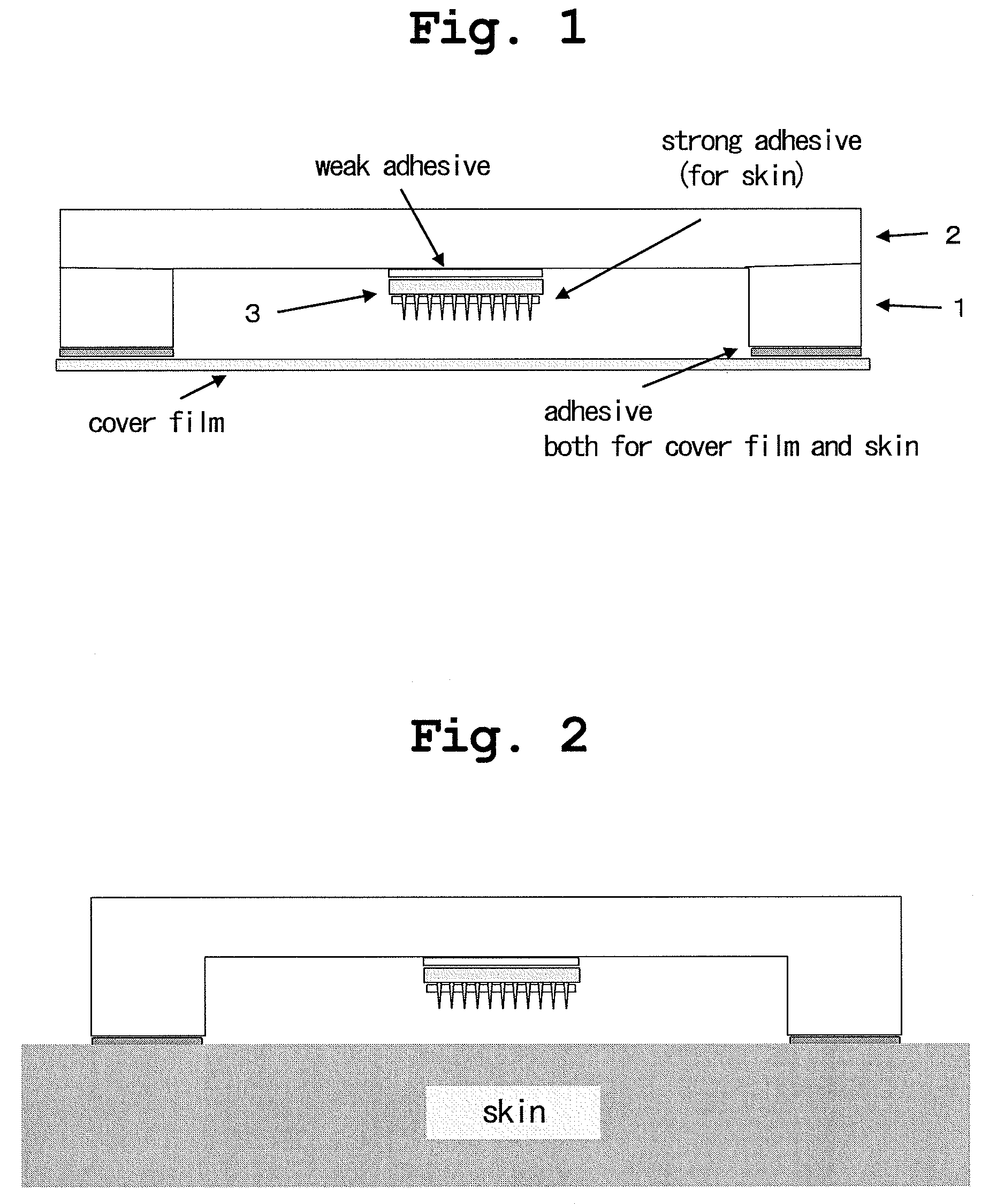
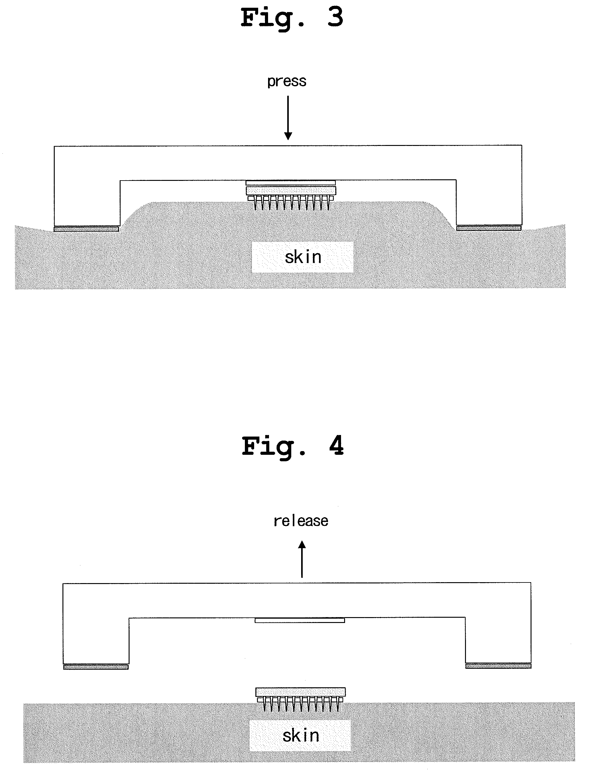
[0027]Pressing the device of the present invention against the skin enables puncture of the skin, hardly causing breakage of the small needles, even though the microneedle is made of a biodegradable resin that has insufficient material strength. Further, since the device of the present invention is in the form of a small chip, it is easily portable, with the concave part being covered, and even ordinary people can remove the cover and administer a drug transdermally in a convenient manner.

Problems solved by technology

However, due to the barrier action of the stratum corneum described above, absorption of drug-effective components is insufficient.
These puncturing methods of the microneedle using impact force, however, may cause easy breakage of the small needles of the microneedle in the step of puncturing the skin and also cause excessive damage to the skin surface.

Method used


Image

  • Applicator for microneedle array
  • Applicator for microneedle array
  • Applicator for microneedle array

Examples


example 1

Production of the Microneedle Device Having a Circular Concave Part

[0077]By using a method shown in FIG. 9, a supporting member 1 (material: polypropylene, 3×3 cm) having a thickness of 2.3 mm through which an circular opening (diameter: 2.5 mm) was formed was produced, and to this, a fixing member 2 (material: polypropylene, 3×3 cm) having a thickness of 1 mm was bonded by melting, and thus a chip having a concave part was produced as shown in FIG. 10.

[0078]Next, a microneedle (1 cm×1 cm) made of PLA that was described in WO2008 / 093679 were fixed to a central part of the bottom part by means of an adhesive (double-sided tape, manufactured by Nichiban Co., Ltd.) to obtain a device shown in FIG. 11. As the microneedle made of PLA, a sample with a base having a thickness of 1 mm and small needles having a length of about 500 μm was used as shown in FIG. 12.

example 2

Production of the Microneedle Device Having Various Concave Part

[0079]In accordance with Example 1, devices in which the sizes of the circular openings were changed as shown in Table 1 were produced. Further, devices in which the shapes of the openings were changed from the circular shape to square or rectangular shape as shown in Table 1 were produced. Here, the size of each fixing member constituting the bottom part was changed depending on the shape of the opening, and set to be about 5 mm longer than the length of diameter, long side, and short side. The thickness of the supporting member having the opening was 1.8 mm.

[0080]

TABLE 1shape of openingdiameter of opening (mm)circular51015202530325772long sideshort sideaverage(mm)(mm)(mm)square151515202020303030rectangular201517.5302025301522.5

[0081]Next, in a central part of the obtained device, the microneedle of Example 1 was placed by means of double-sided tape, to obtain a microneedle device as shown in FIG. 11.


PUM


Abstract

Provided is a microneedle device which protects microneedle, has an easily portable shape, is free from such problems as breakage of small needles in the step of puncturing the skin with the microneedle, and ensures appropriate skin puncture for administering a drug. By studying the relationship between a device to be pressed to the skin and the height of an elevation on the skin surface under the pressing and thus producing a device equipped with microneedle that are embedded in a concave part having a definite depth, the microneedle can be surely and easily inserted and punctured into the skin while avoiding such problems as breakage of the small needles of the microneedle. Thus, a microneedle patch formulation, which is easily portable and ensures convenient drug administration to the skin, can be produced.

Description

TECHNICAL FIELD[0001]The present invention relates to an applicator used to puncture skin with a pin-frog-shaped (kenzan-shaped) microneedle effectively. Also, the present invention relates to a method for plastering a patch formulation using the pin-frog-shaped microneedle.BACKGROUND ART[0002]Transdermal administration of drugs has been normally achieved by using formulations for transdermal administration in the form of solutions or ointments to be applied or plastered to the skin surface. The skin, in the case of human, normally comprises a number of tissues: the stratum corneum (horny layer) having a laminar structure in a thickness of 10 to 30 μm, the epidermal tissue layer in a thickness of about 70 μm, and the dermal tissue layer in a thickness of about 2 mm.[0003]The stratum corneum, which is a laminar structure constituting the outermost layer of the skin, functions as a barrier to prevent various drugs from penetrating the skin. Generally, about 50 to 90% of the barrier ac...

Claims


Application Information

Patent Timeline
Patent Type & Authority Patents(United States)
IPC IPC(8): A61M5/00A61F13/00
CPCA61M37/0015A61M5/425A61M2037/0023
Inventor KOBAYASHI, KATSUNORIHAMAMOTO, HIDETOSHI
Owner MEDRX CO LTD
Learn More