Detector-shift type combined radiation therapy/PET apparatus

a combined radiation therapy and cat technology, applied in the field of cat-shift-type combined radiation therapy/pet devices, can solve the problem of not being able to create a precise image of the irradiation field, and achieve the effect of improving the image quality of the entire open space, suppressing local sensitivity drops in the open area, and high s/n

Inactive Publication Date: 2013-11-12
NAT INST FOR QUANTUM & RADIOLOGICAL SCI & TECH
View PDF17 Cites 32 Cited by
  • Summary
  • Abstract
  • Description
  • Claims
  • Application Information

AI Technical Summary

Benefits of technology

[0015]The present invention has been achieved to solve the foregoing conventional problems. It is thus an object of the present invention to prevent a performance degradation or a failure of the detectors due to the radiation irradiation, and create an image of the distribution of short-lived nuclides so as to cover up to the peripheral areas of the irradiation field.
[0016]The present invention includes: an open PET device including a plurality of detector rings that are arranged to be opposed to each other in a direction of a body axis and perform radiation measurement inside bores thereof; and a radiation irradiation device that is capable of irradiation with a radiation through a space between mutually-adjoining ones of the detector rings, thereby forming an irradiation field in the space. At least either one of two space-forming detector rings forming the space is a movable detector ring. The movable detector ring is located in a retreated position away from the irradiation field so as to avoid damage from irradiation during the radiation irradiation, and performs radiation measurement while moving on an irradiation-field side of the retreated position after the irradiation. Consequently, a performance degradation or a failure of the detectors due to the beam is prevented, and radiation measurement is performed in close proximity to the irradiation field to create an image of the distribution of short-lived nuclides in the vicinity of the irradiation field.
[0025]In the present invention, the detectors are located away from the irradiation field during beam irradiation. The detectors are moved toward the irradiation field immediately after the end of the beam irradiation as quickly as possible so that the PET measurement is performed with a large solid angle. The PET measurement is also performed on the approach, collecting more PET measurement data. This makes it possible to measure radiation occurring from short-lived nuclides efficiently with a high S / N ratio.
[0026]Since local sensitivity drops in the open area are suppressed, it is possible to improve the image quality of the entire open space including the peripheral areas as well as the center of the open space.

Problems solved by technology

In such a position, it is not possible to create a precise image of the irradiation field due to a significant drop in sensitivity in the periphery of the open area, as well as a small solid angle.

Method used


Image

  • Detector-shift type combined radiation therapy/PET apparatus
  • Detector-shift type combined radiation therapy/PET apparatus
  • Detector-shift type combined radiation therapy/PET apparatus

Examples


first embodiment

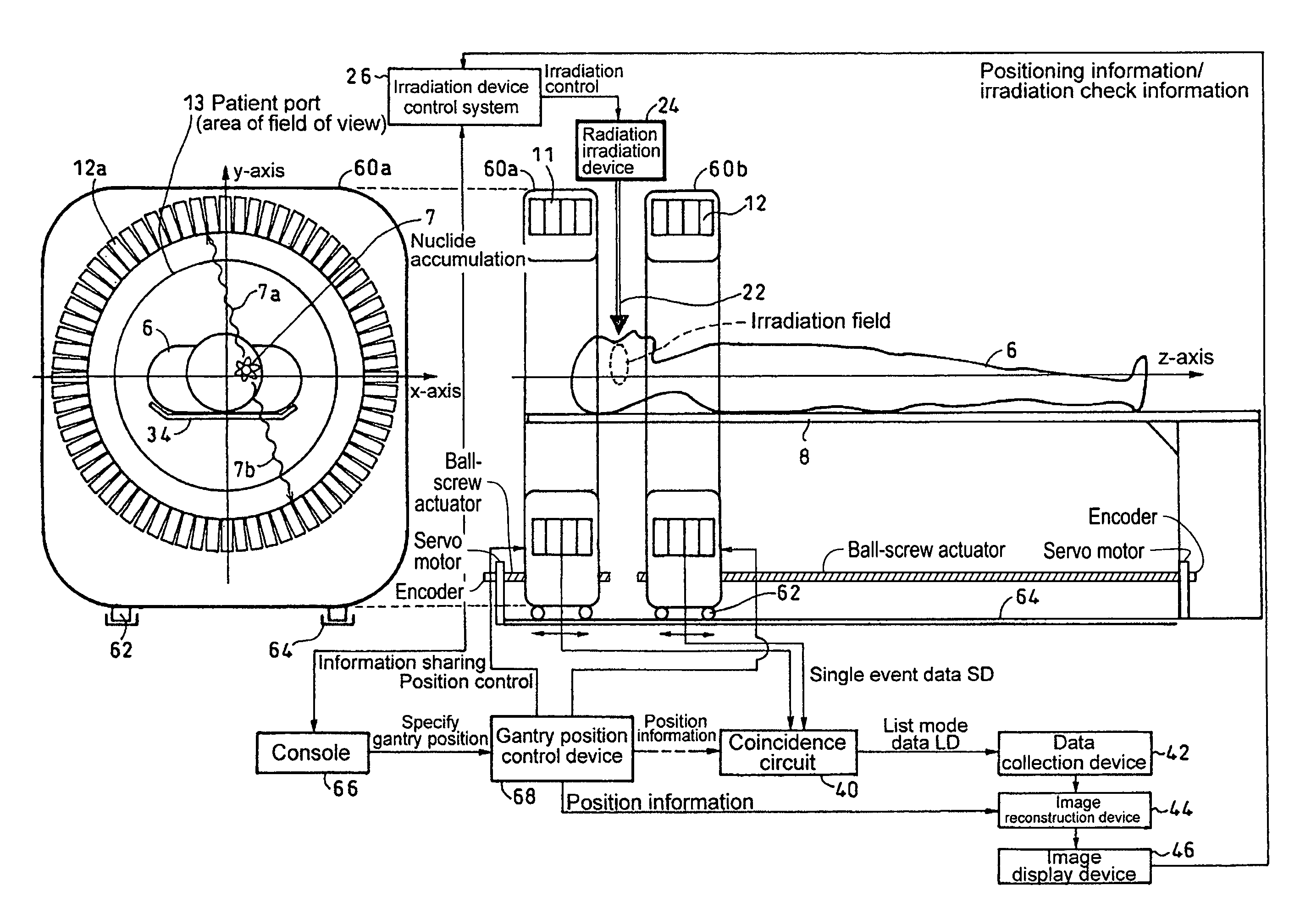
[0063]Next, a description will be given of an embodiment of the present invention where the open PET device is applied to beam monitoring in radiation therapy. FIG. 14 shows the configuration of a Two identical ring-shaped detector rings (space-forming detector rings) 11 and 12 are arranged in parallel as independent gantries (60a, 60b), and a radiation irradiation device 24 is inserted into the space between the detector rings 11 and 12, whereby treatment monitoring of observing one and the same treated area immediately after treatment by PET is implemented.

[0064]Specifically, the embodiment includes the detector rings 11 and 12, gantry covers 60a and 60b which cover the respective detector rings, and a bed 8 on which a patient 6 lies. The gantries are each equipped with wheels 62, and have the function of moving in the direction of the body axis on common or different rails 64.

[0065]A therapy beam 22 produced from the radiation irradiation device 24 passes through the spatial gap...

second embodiment

[0078]Next, the present invention where a detector shift (parallel shift) is applied to spot scanning irradiation will be shown in FIG. 16. The diagram shows the spot scanning irradiation in which the irradiation field is further divided into a plurality of layers of zones parallel to the detector rings. The layers are each scanned and irradiated with the beam spot, moving from one layer to another in succession. With the center of a tumor or other reference position as m0, the reference positions of the left and right detector rings when the center of the open area falls on m0 will be referred to as p0 and q0, respectively. In the spot scanning irradiation, the tumor is scanned with pencil beam irradiation in a short time so that the entire tumor is covered with spot-like irradiation fields. After the irradiation, the detector rings are parallel shifted in the direction of the body axis so as to follow the layer movement of the spot scanning irradiation, whereby the distribution of...

fourth embodiment

[0088]Now, a description will be given of a fourth embodiment which is another mode of operation of the basic two detector rings and radiation irradiation device shown in FIGS. 4 and 5(B).

[0089]On the time chart shown in FIG. 5(B), the detector rings move on the approach to reach the predetermined position (P4) closest to the irradiation field and then immediately move on the return. FIG. 23 shows a time chart where the detector rings reaching the position make a stop until the end of the PET measurement, and then move on the return to their retracted position.


PUM


Abstract

In beam monitoring for detecting annihilation radiations produced by radiation irradiation in radiation therapy for cancer which is performed by irradiating the affected area by X-rays, gamma rays, or particle beams, a detector-shift type combined radiation therapy / PET apparatus is provided with an open PET device that includes a plurality of shiftable multi-ring detector rings; and a radiation irradiation device that is capable of irradiation with a radiation beam through between the detector rings. The apparatus changes the positions of the detector rings, performs irradiation with the radiation beam through between the detector rings, and then performs radiation measurement.

Description

TECHNICAL FIELD[0001]The present invention relates to a detector-shift type combined radiation therapy / PET device which can efficiently measure radiation occurring from short-lived nuclides at the time of monitoring for detecting annihilation radiation produced by radiation (also referred to as beam) irradiation in radiation therapy for cancer which is performed by irradiating the affected area with X-rays or particle beams, even if, in particular, the detectors are located away from the irradiation field during the beam irradiation.BACKGROUND ART[0002]Positron emission tomography (PET) is attracting attention as an effective test method for earlier diagnosis of cancer. In PET, a compound labeled with a trace amount of positron emitting nuclides is administered and annihilation radiation emitted from inside the body is detected to create an image of metabolic functions such as sugar metabolism and check for a disease and its extent. PET devices for practicing PET have been put into ...

Claims


Application Information

Patent Timeline
Patent Type & Authority Patents(United States)
IPC IPC(8): G01T1/161
CPCA61B6/037A61B6/4266A61N5/1048G01T1/2985A61N2005/1052A61N2005/1087
Inventor YAMAYA, TAIGAMURAYAMA, HIDEOMINOHARA, SHINICHIINANIWA, TAKUFURUKAWA, TAKUJIMORI, SHINICHIROU
Owner NAT INST FOR QUANTUM & RADIOLOGICAL SCI & TECH
Why Eureka
Try Eureka