Supercharge Your Innovation With Domain-Expert AI Agents!

Movie reproduction system and movie reproduction method for reducing delay time of reproduced movie

a technology of movie reproduction and movie delay, which is applied in the field of movie reproduction system and movie reproduction method for reducing delay time of reproduced movie, can solve the problems of large delay time, large communication rate limit, and generation of delay time between image generation and image reproduction, so as to reduce the delay time and reduce the delay time. , the effect of reducing the delay tim

Inactive Publication Date: 2013-11-12
MEGACHIPS
View PDF20 Cites 7 Cited by
  • Summary
  • Abstract
  • Description
  • Claims
  • Application Information

AI Technical Summary

Benefits of technology

The invention is a system for reproducing movies using communication data. The system synchronizes starting time data with the communication clock of the receiving means to shorten delays. The communication data includes start time data and movie data, and the system generates the second vertical synchronizing signal based on the start time data and the communication clock. The invention also prioritizes the sending of the start time data and generates the second vertical synchronizing signal with higher accuracy. The system can improve the accuracy of the second vertical synchronizing signal by sending the communication data separately or prioritizing it. The invention does not need to send separate frame timing data and can use the movie data as the frame timing data.

Problems solved by technology

Like those systems, in a case of using data communication between the image generation apparatus and the image reproduction apparatus, there is a problem that, because size of movie data is relatively large, a delay time is generated between image generation and image reproduction mainly because of delay in transmission.
Especially in a case of using wireless data communication, data has to be sent / received within a limited bandwidth and therefore there is an upper limit to the communication rate.
Thus, reduction in the delay time is a large problem.
Even if the play screen is reproduced at a constant frame interval (even if the play screen is smoothly and continuously reproduced), when the play screen is presented behind the player's operation, the player feels a feeling of strangeness in operation and this lowers operability.
In other words, in specific technical fields, merely reproducing the movie continuously on the reproduction side is not sufficient, but being real-time in the reproduction of movie is further required.

Method used


Image

  • Movie reproduction system and movie reproduction method for reducing delay time of reproduced movie
  • Movie reproduction system and movie reproduction method for reducing delay time of reproduced movie
  • Movie reproduction system and movie reproduction method for reducing delay time of reproduced movie

Examples


first embodiment

1. First Embodiment

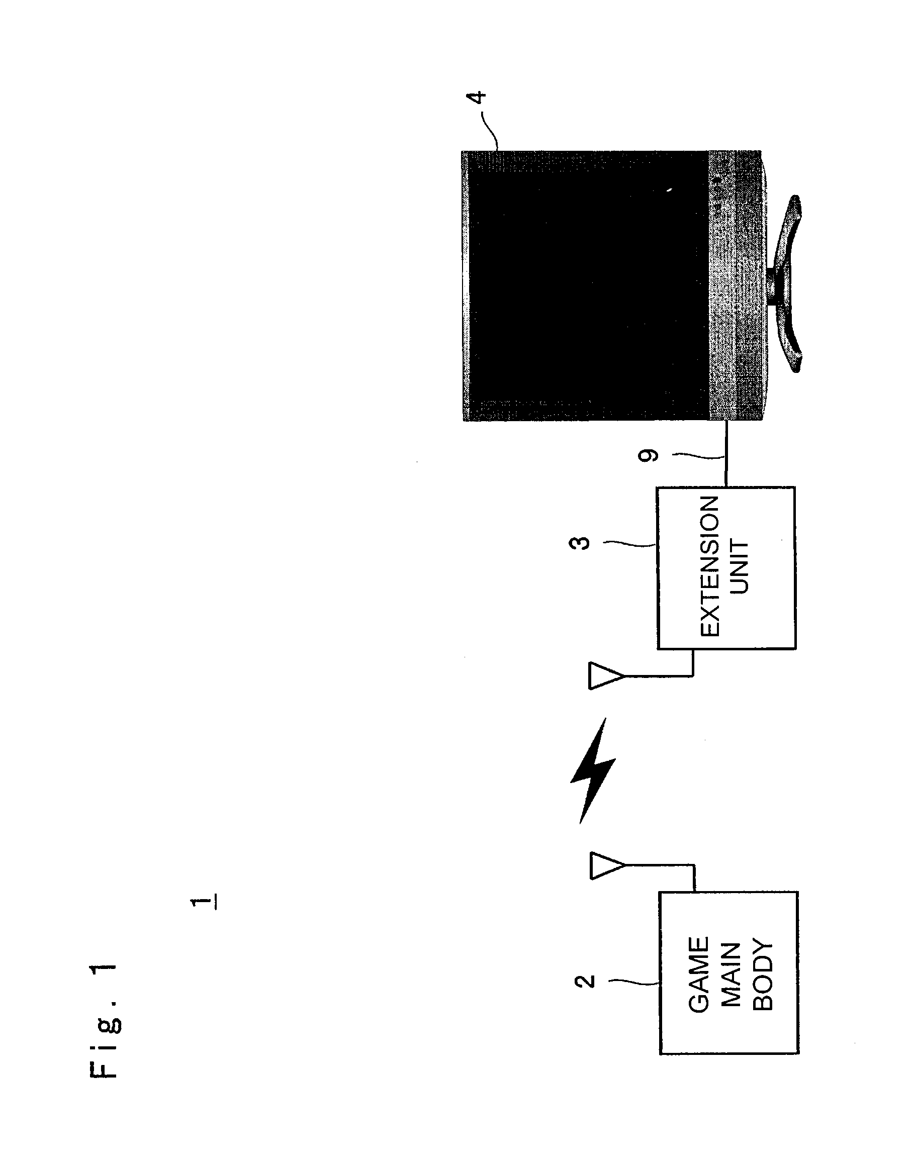
[0083]FIG. 1 is a diagram showing the structure of a movie reproduction system 1 according to the present invention. The movie reproduction system 1 is arranged as a system which is formed by a game main body 2, an extension unit 3, a TV receiver 4, and a cable 9 and which wirelessly sends / receives a movie between the game main body 2 and the extension unit 3 and reproduces the movie on the TV receiver 4.

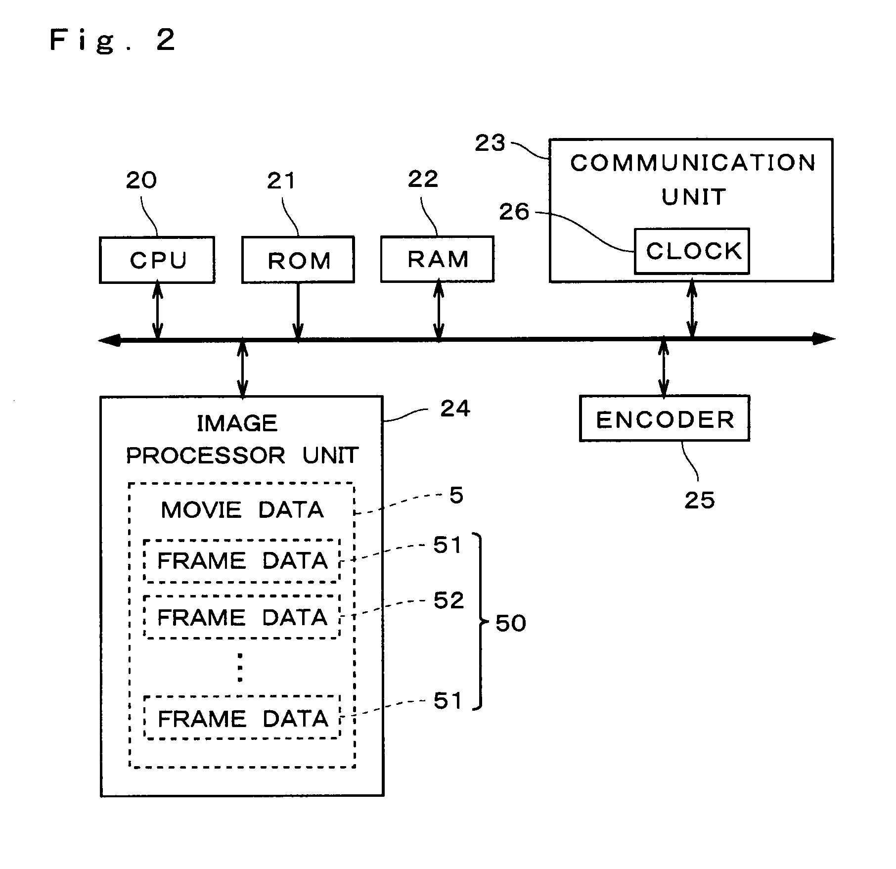
[0084]FIG. 2 is a block diagram showing the structure of the game main body 2 in the first embodiment. The game main body 2 includes a CPU 20 for performing calculation of various kinds of data and generation of control signals, a read-only ROM 21 in which data such as a start-up program is stored, and a RAM 22 used as a temporal working area of the CPU 20.

[0085]Although not shown in FIG. 2, the game main body 2 includes: a reader unit for reading game programs (data supplied while being stored in a medium such as a CD-ROM, a cartridge, and a memory card); an inpu...

second embodiment

2. Second Embodiment

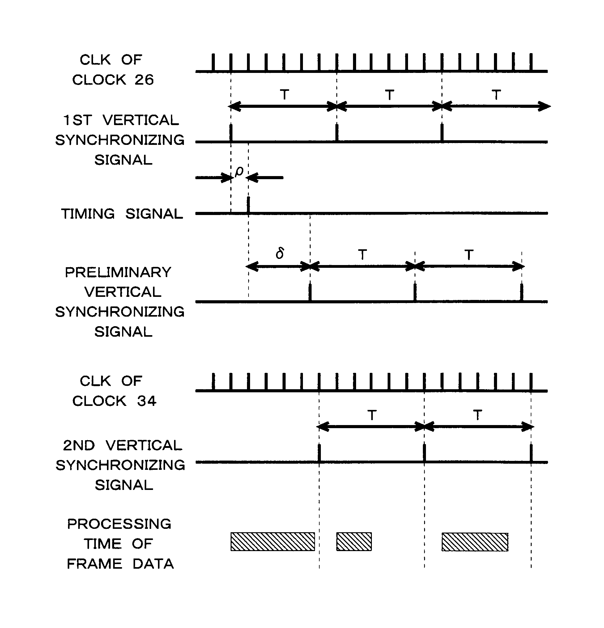
[0171]In the first embodiment, an example is described in which two communication clocks (clocks 26 and 34) which are provided on a movie data generation side and a movie data reproduction side, respectively, and are synchronized with each other are used for synchronizing a vertical synchronizing signal for movie data generation (first vertical synchronizing signal) and a vertical synchronizing signal for movie data reproduction (second vertical synchronizing signal) with each other. However, the technique for synchronizing the first vertical synchronizing signal and the second vertical synchronizing signal with each other is not limited to the example described in the first embodiment.

[0172]FIG. 9 is a block diagram showing the structure of the game main body 2 in the second embodiment. The game main body 2 in the second embodiment is different from that in the first embodiment in that an image processor unit 24a is provided instead of the image processor unit 2...

third embodiment

3. Third Embodiment

[0217]In the second embodiment, the system is arranged such that the frame timing data and the movie data (frame data) are sent as separate communication data from each other. However, the system can be arranged such that the movie data received as the communication data on the receiving side is also used as the frame timing data and the second vertical synchronizing signal is generated in accordance with a time at which the movie data is received.

[0218]The third embodiment can be implemented by the same structure of the movie reproduction system 1 in the second embodiment. Therefore, the same reference signs as those in the movie reproduction system 1 in the second embodiment are used and the description of the third embodiment is omitted in an appropriate manner.

[0219]The image processor unit 24a of the movie reproduction system 1 in the third embodiment does not output the first vertical synchronizing signal to the communication unit 23.

[0220]In general, a head...


PUM


Abstract

After a sending-side clock and a clock 34 of a communication unit 33 on a receiving side are synchronized with each other, the first vertical synchronizing signal is generated in accordance with the sending-side clock, and movie data 5 representing a movie is generated by generating frame data in accordance with the generated first vertical synchronizing signal. Start time data indicating the time for starting generation of the movie data 5 and the movie data 5 are sent as communication data from the sending side to the communication unit 33. Then, the second vertical synchronizing signal is generated in accordance with the clock 34 of the communication unit 33 and the start time data received as the communication data. The frame data 50 included in the movie data 5 received as the communication data is presented in accordance with the second vertical synchronizing signal.

Description

TECHNICAL FIELDS[0001]The present invention relates to techniques for sending data representing a movie through communication and reproducing (displaying) the movie on the receiving side. In particular, the present invention relates to techniques for suppressing a time of delay occurring on the receiving side.BACKGROUND ART[0002]Movie reproduction is achieved by sequentially displaying still images (frames) at a constant time interval (hereinafter, referred to as a “frame interval”) by means of an image reproduction apparatus such as a display.[0003]On the other hand, systems have been proposed which convert a movie signal generated by an image generation apparatus into digital data and send it to the image reproduction apparatus set at a remote location through data communication to reproduce it (a broadcasting system, a monitoring system, a TV phone system, a game system, and the like). Like those systems, in a case of using data communication between the image generation apparatu...

Claims


Application Information

Patent Timeline
Patent Type & Authority Patents(United States)
IPC IPC(8): H04N9/475H04N21/236H04N21/426H04N21/431H04N21/4363H04N21/44
CPCG09G5/008H04N21/4305H04N21/4122G09G2370/16
Inventor SAWADA, TAKASHI
Owner MEGACHIPS
Features
  • R&D
  • Intellectual Property
  • Life Sciences
  • Materials
  • Tech Scout
  • Unparalleled Data Quality
  • Higher Quality Content
  • 60% Fewer Hallucinations
Learn More