
Panel, especially floor panel

a technology for floor panels and panels, applied in the field of floor panels, can solve the problems of poor quality, insufficient stiffness of these connections, and complex profiling of side edges, and achieve the effect of improving the profiling of hook elements and ensuring reliable interlocking

Inactive Publication Date: 2013-11-19
VÄLINGE INNOVATION AB
View PDF13 Cites 8 Cited by
  • Summary
  • Abstract
  • Description
  • Claims
  • Application Information

AI Technical Summary

Benefits of technology

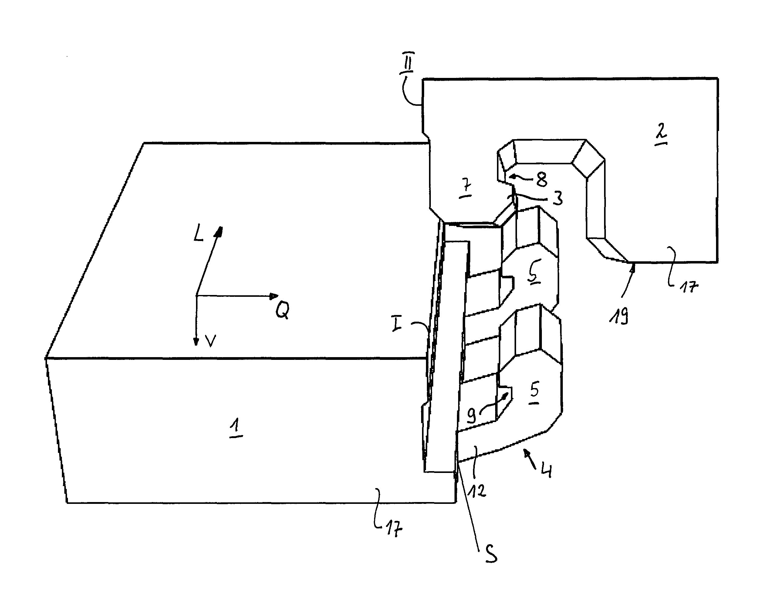
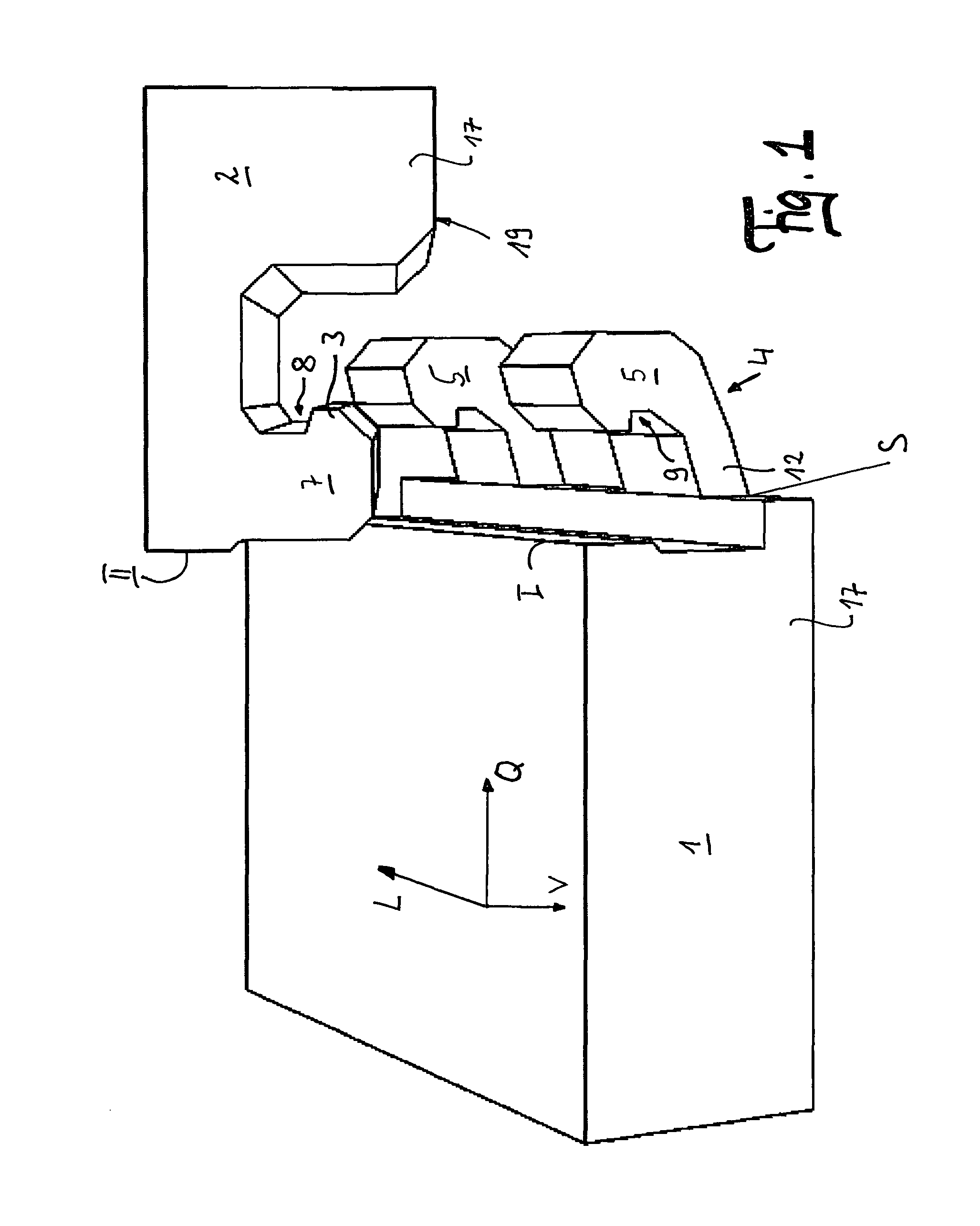
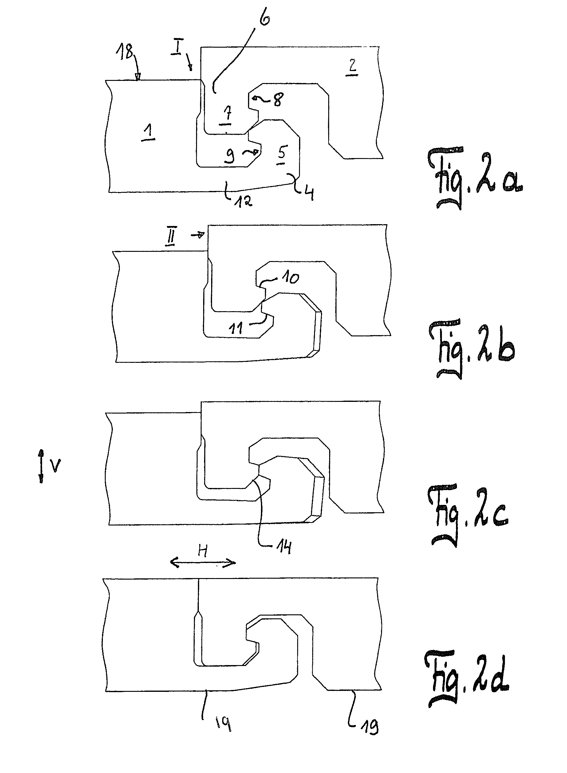
The patent text describes an improvement to a panel that allows for better interlocking between panels. The improved design allows for larger interlocking surfaces and reliable interlocking, especially on the transverse side of the panels. The hook elements on the side edges interlock two panels in both the horizontal and vertical direction, and the elastically deflectable projections of the hook elements snap back to their initial position, creating vertical interlocking. The tongue elements run at an angle to the side edge, allowing for more space and more reliable interlocking. The interlocking surface is larger due to the oblique surface, making it more reliable. The design also makes it easier to install panels because the bottom hook element allows for a more uniform lowering motion.

Problems solved by technology

At a small panel thickness, especially for panels with a thickness of 6 or 7 mm, the stiffness of these connections is often not sufficient.
In conventional tests with steel rolls (DIN 13329) slight vertical offsets between adjacent panels can arise due to multiple cyclic loading, especially in the region of the transverse-side interlocking; this becomes immediately apparent with unfavorable light incidence, by which the floor coating can engender the impression of poor quality.
This profiling of the side edges is mechanically very complex and installation of the panels becomes in part more complicated since it must be ensured that the tongues are plunged into the grooves over the full length of the side edges.
If then the concluding interlocking motion is not carried out completely parallel to the lengthwise axis of the panel, there is the danger that the panel to be interlocked will be tilted and will swivel the tongue out of the groove so that interlocking is no longer possible.

Method used


Image

  • Panel, especially floor panel
  • Panel, especially floor panel
  • Panel, especially floor panel

Examples


Embodiment Construction

[0039]The aforementioned described profile connection has the advantage that it is machined in one piece out of the core material, does not require any outside parts and thus fewer production tolerances need be maintained than otherwise. As a result of the higher stiffness, several forces can be transferred in the vertical direction. The profiling is also suitable for thin panels and tools which can move only on one side, preferably plunge cutters, are necessary for production. Production takes place essentially as described in DE 10 2007 015 048 A1. For producing the undercuts 8, 9 the hook elements 4, 5 are machined by means of a vertical tool which is not shown. The slots 13 which run obliquely to the longitudinal axis L of the panel are produced by cutting tools which plunge into the core 17 in the vertical direction V while the panel 1 is moving past the machining station (not shown). Since the plunging cutting tools are oblique to the transport direction, they must be ground s...


PUM


Abstract

A panel, especially floor panel comprises a core produced of a wood product or a mixture of a wood product / synthetic material. The panel includes a top and a bottom, and is provided with mating hook elements on at least two opposite lateral edges thereof. The first hook element is formed by a profiled section which is essentially open to the top and the second hook element is formed by a profiled section which is essentially open to the bottom. The profiled section on the first hook element forms a projection which is essentially facing the top and on the second hook element forms a projection which is essentially open to the bottom. Two identical panels can be interconnected and interlocked by an essentially vertical joining movement in the horizontal and the vertical direction. At least one of the projections is deviated during the joining movement in the horizontal direction and then snaps into a locking edge which extends essentially in the horizontal direction to vertically lock the panels. At least one of the hook elements has a segmented design, thereby forming a plurality of parallel interspaced spring elements. The panel according to the invention is characterized in that the spring elements are diagonally arranged at an angle to the longitudinal axis.

Description

BACKGROUND OF THE INVENTION[0001]1. Field of the Invention[0002]The invention relates to a panel, especially a floor panel, with a core of wood product or wood product-plastic mixture, a top and a bottom which is provided with hook elements which correspond to one another on at least two opposite side edges, the first hook element being formed by profiling which is essentially open to the top and the second hook element being formed by profiling which is essentially open to the bottom and which on the first hook element forms a projection which is pointed essentially toward the top and on the second element a projection pointed essentially toward the bottom, and at least one of the hook elements being a spring element which deviates in the horizontal direction in the joining motion and then for purposes of vertical interlocking snaps in behind an interlocking edge which extends essentially in the horizontal direction, and at least one of the hook elements being segmented and a plura...

Claims


Application Information

Patent Timeline
IPC IPC(8): E04B2/00
CPCE04F15/02F16B5/0056Y10T428/167E04F2201/0138
Inventor BRAUN, ROGER
Owner VÄLINGE INNOVATION AB
Learn More