Method and system for controlling solid propellant thrust

a propellant thrust and solid technology, applied in the field of propulsion systems, can solve the problems of inert weight, poor mass fraction, inert weight, etc., and achieve the effects of reducing inert weight, increasing rocket motor mass fraction, and simplifying controllable rocket motors

Inactive Publication Date: 2013-11-19
DIGITAL SOLID STATE PROPULSION
View PDF6 Cites 29 Cited by
  • Summary
  • Abstract
  • Description
  • Claims
  • Application Information

AI Technical Summary

Benefits of technology

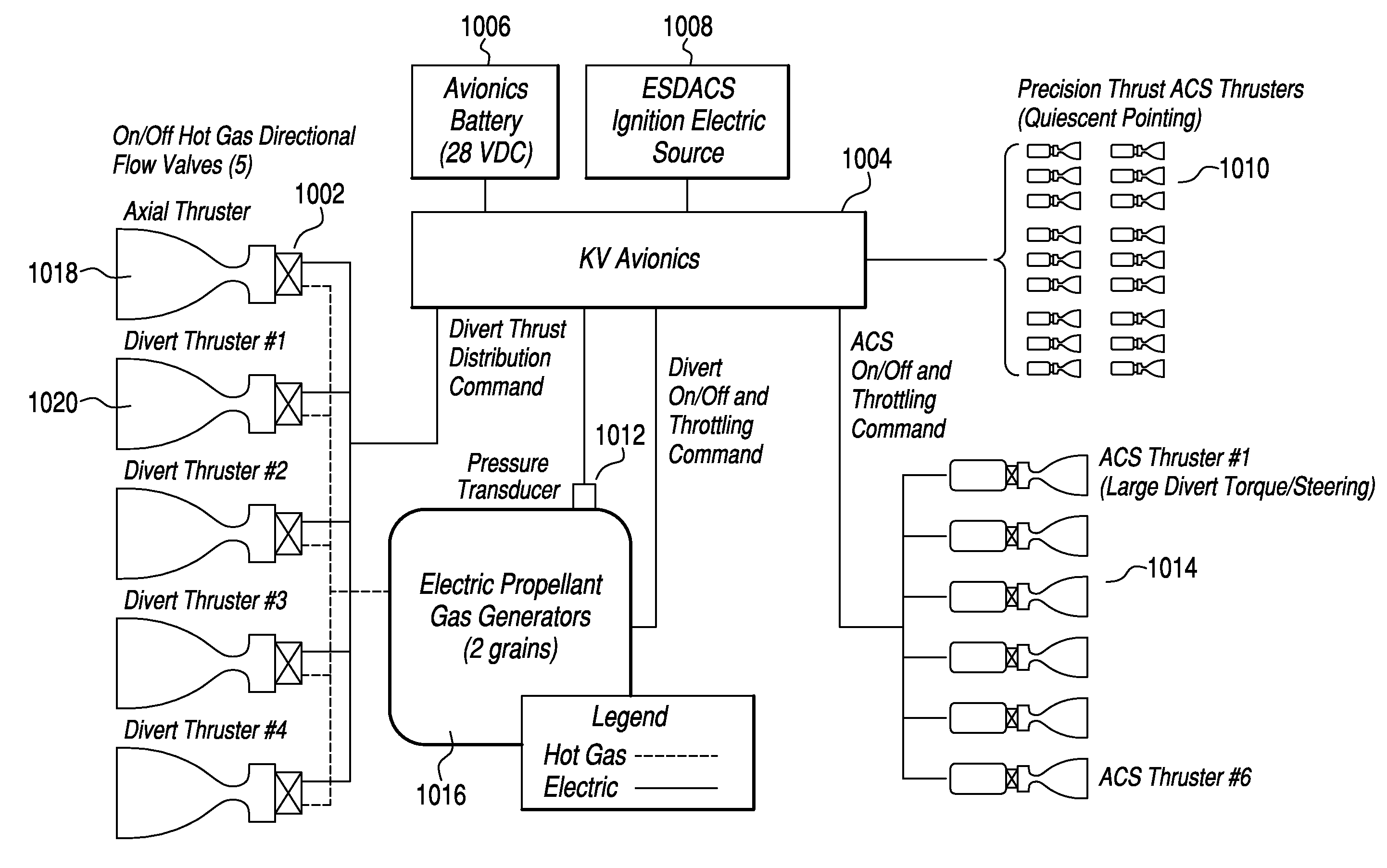
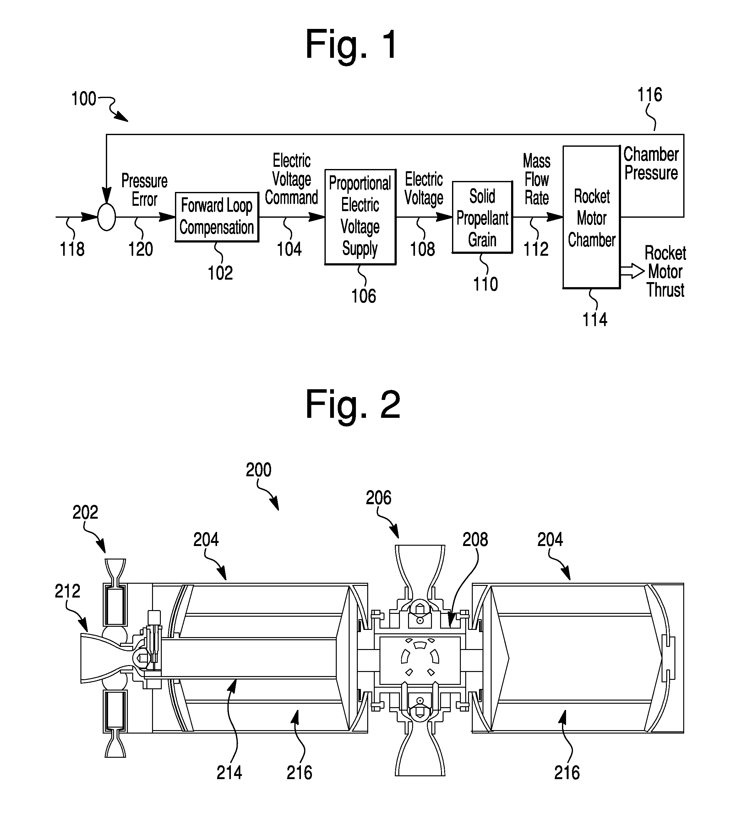
[0009]According to some aspects of the invention, the control system uses a closed loop algorithm to control the amount of electrical power applied to the solid propellants to cause them to output a desired amount of thrust. The result is rocket motor thrust varying proportionally with the propellant burn rate without using variable throat area pintle nozzles. Due to this, numerous improvements can be made to the future controllable solid rocket motor systems, including but not limited to: Rocket motor components are eliminated thus reducing the inert weight and increasing rocket motor mass fractions up to 60%; The controllable rocket motor is simplified thus reducing production cost by up to 50%; Overall rocket motor performance is increased due to the removing of pintle nozzles—Up to 20% performance increase in nozzle thrust efficiency results; Rocket motor thrust control is one to one with burn rate control improving thrust accuracy; Rocket motor ignition and extinguishment transients are improved and simplified by application and removal of electric voltage / current to perform rocket motor impulse control; the electrically controlled propellants inherently posses “Insensitive Munitions” capabilities that meet future defense requirements. These features are critical to ensure the propellant is safe for being deployed on fighter aircraft.

Problems solved by technology

This is despite the fact that most of the gas is vented uselessly, because control is needed during only about 30% of the flight.
Unfortunately, pintle nozzles have several drawbacks: they add significant inert weight to a system with an already poor mass fraction, they reduce nozzle efficiencies thereby reducing performance, during the extinguishment event they create thrust spikes by opening the nozzle throats, and they can have significant thruster misalignment problems due to the necessity of their being mounted on the outside of the chamber.
Additionally, a pintle nozzle control system can only correct upon measured chamber pressure by varying the rocket motor throat area.
Due to propellant ballistic burn rate errors at controlled pressures, resulting thrust has inherent inaccuracies that can only be corrected by the vehicle flight control system as measured through inertial sensors.

Method used


Image

  • Method and system for controlling solid propellant thrust
  • Method and system for controlling solid propellant thrust
  • Method and system for controlling solid propellant thrust

Examples


Embodiment Construction

[0018]The present invention will now be described in detail with reference to the drawings, which are provided as illustrative examples of the invention so as to enable those skilled in the art to practice the invention. Notably, the figures and examples below are not meant to limit the scope of the present invention to a single embodiment, but other embodiments are possible by way of interchange of some or all of the described or illustrated elements. Moreover, where certain elements of the present invention can be partially or fully implemented using known components, only those portions of such known components that are necessary for an understanding of the present invention will be described, and detailed descriptions of other portions of such known components will be omitted so as not to obscure the invention. Embodiments described as being implemented in software should not be limited thereto, but can include embodiments implemented in hardware, or combinations of software and...


PUM


Abstract

The present invention relates to a solid rocket motor control system that uses state of the art electrically ignited, extinguishable and throttleable propellants. In embodiments, the control system is implemented by a software algorithm embedded in missile flight controllers and contains all control system elements and control compensation that performs thrust control for many defense and space rocket motor applications, for example.

Description

CROSS-REFERENCE TO RELATED APPLICATIONS[0001]The present application claims priority to U.S. Prov. Appln. No. 61 / 097,437, filed Sep. 16, 2008, the contents of which are incorporated herein by reference in their entirety.FIELD OF THE INVENTION[0002]This invention resides in the field of propulsion systems, and in particular to systems that can freely control the amount thrust output from solid propellants.BACKGROUND OF THE INVENTION[0003]Solid propellants have numerous advantages over liquids for missile propulsion and as gas generators. Among these are greater safety in storage, handling, and transport, higher density, and simplicity of propellant packaging. Liquid propellants, however, have traditionally offered the huge advantage of ease of throttling and can be extinguished and reignited at will, thereby offering better energy management with minimal waste of on-board propulsive resources.[0004]One application for this invention is in the Divert and Attitude Control Systems (DACS...

Claims


Application Information

Patent Timeline
Patent Type & Authority Patents(United States)
IPC IPC(8): F02K9/00
CPCF02K9/08F02K9/26
Inventor CARLSON, RUSSELL W.
Owner DIGITAL SOLID STATE PROPULSION
Why Eureka
Try Eureka