RF directional coupler circuit assembly for matching high frequency cable TV apparatus

a technology of directional couplers and high-frequency cable tvs, which is applied in the direction of two-way working systems, television systems, and television connectors, etc., can solve the problems of cable tv signal serious fading, cable tv signal fading, so as to reduce the fading of transmitted high-frequency signals

Inactive Publication Date: 2013-11-19
CABLE VISION ELECTRONICS
View PDF4 Cites 7 Cited by
  • Summary
  • Abstract
  • Description
  • Claims
  • Application Information

AI Technical Summary

Benefits of technology

[0007]Therefore, an object of the present invention is to solve the disadvantages of the conventional cable TV apparatus. The present invention is to provide a design shortening the distance between the printed circuit board and the bottom surface of the cover body, for improving high frequency impedance matching for RF directional coupler circuits inside RF directional couplers and signal taps of high frequency cable TV apparatus.
[0008]Another object of the present invention is to match a metal plate with the layouts or components on the printed circuit board, to decrease the fading of the transmitted high frequency signals.
[0013]In order to achieve another object mentioned above, the present invention is to mount a metal plate on the printed circuit board. The metal plate is nearby the RF directional coupler circuit on the printed circuit board, so that the metal plate matches the layouts or components on the printed circuit board, to decrease the fading of the transmitted high frequency signals.

Problems solved by technology

Currently the frequencies of the signals of cable TV are higher and higher (1.0 GHz), so that when the signals of cable TV are transmitted, the signals of cable TV are fading, and the image quality of TV in client sites is worse.
When the high frequency signals are transmitted through an RF directional coupler circuit 201 on the printed circuit board 20, there are a lot of signal reflections because of the distance 30, so that the impedance is not matching, the signals of cable TV have serious fading, and the image quality of TV in clients is worse.

Method used


Image

  • RF directional coupler circuit assembly for matching high frequency cable TV apparatus
  • RF directional coupler circuit assembly for matching high frequency cable TV apparatus
  • RF directional coupler circuit assembly for matching high frequency cable TV apparatus

Examples


Embodiment Construction

[0021]Regarding the technology and the detailed description of the present invention, now describe with diagrams as below:

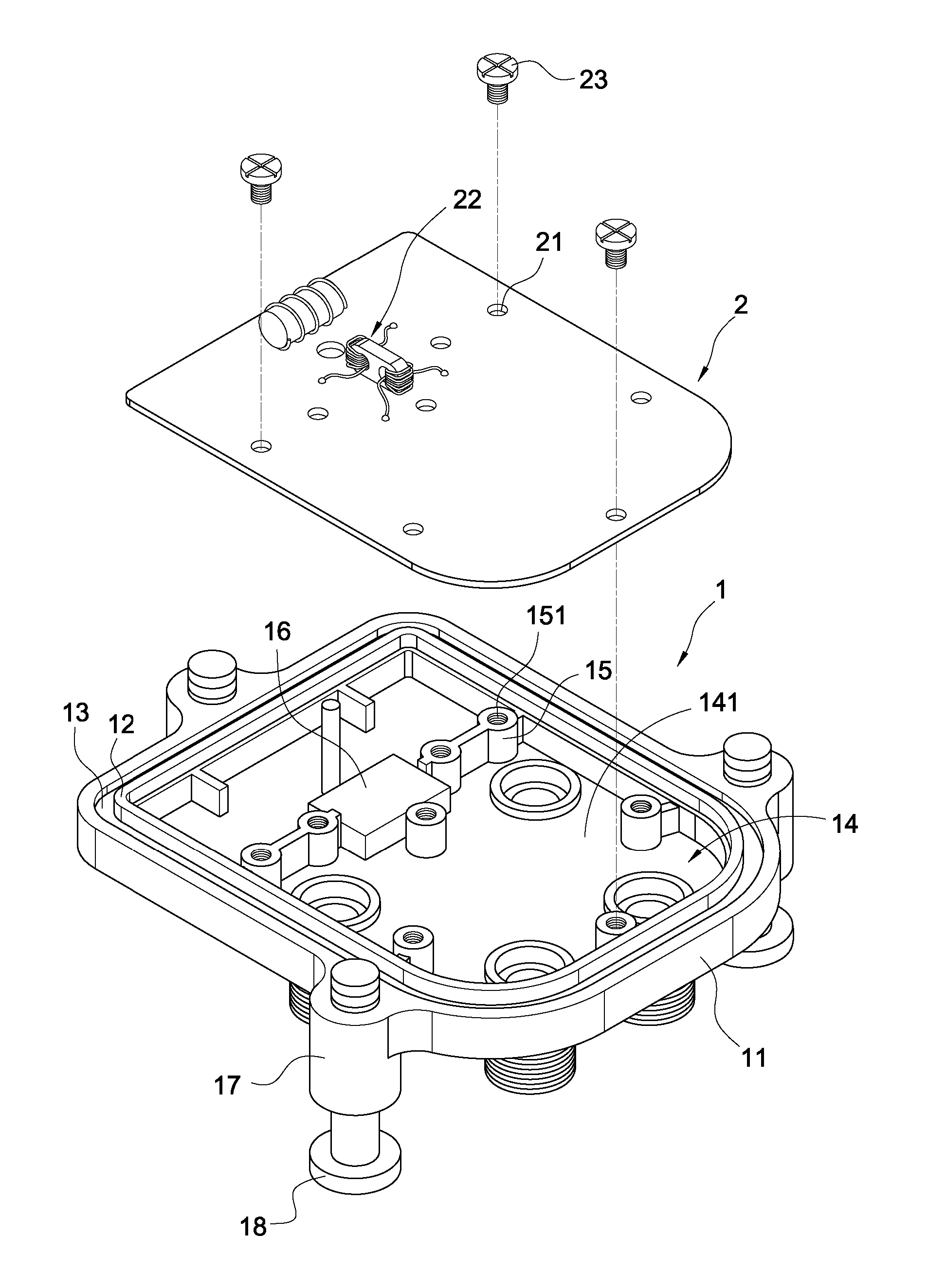
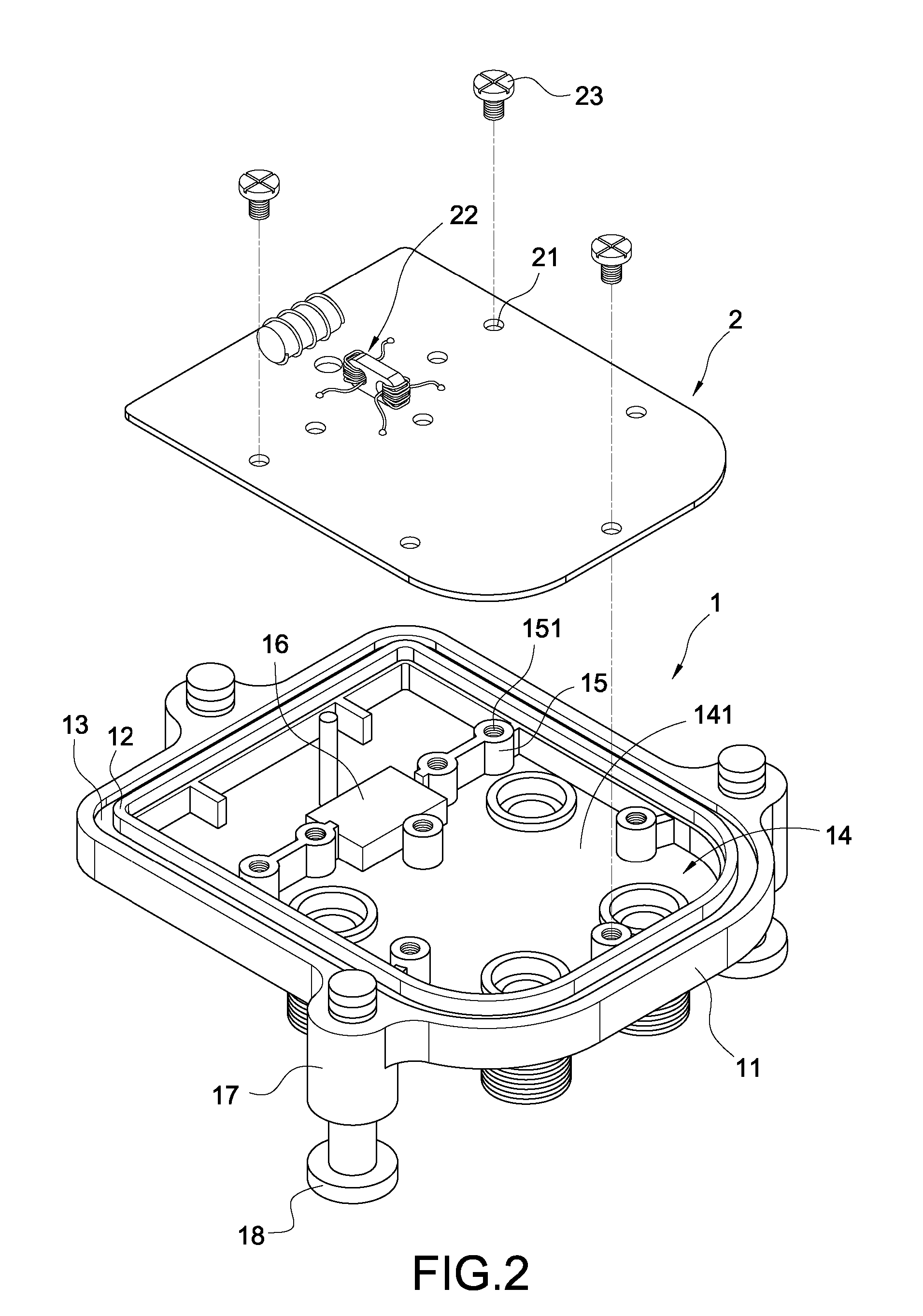
[0022]FIG. 2 shows an exploded view of a high frequency cable TV apparatus of the present invention. FIG. 3 shows a perspective view of a high frequency cable TV apparatus of the present invention. As shown in the FIG. 2 and the FIG. 3, the high frequency cable TV apparatus of the present invention includes a cover body 1, and a printed circuit board 2.

[0023]The cover body 1 includes an edge part 11. An enclosure wall 12 is provided within the edge part 11. A joint trough 13 is between the edge part 11 and the enclosure wall 12. The joint trough 13 is used to assemble the cover body 1 with a base body of the high frequency cable TV apparatus (not shown in the Fig.). Besides, a space 14 is defined in the enclosure wall 12. A plurality of protruding pillars 15 is provided on a bottom surface 141 of the space 14. Each of the protruding pillars 15 includes a threaded...


PUM


Abstract

An RF directional coupler circuit assembly for matching high frequency cable TV apparatus includes a cover body, and a printed circuit board. The cover body includes a space. The space includes a bottom surface. An RF directional coupler circuit is arranged on the printed circuit board. A 0.01 mm˜2 mm gap is formed between the RF directional coupler circuit and the bottom surface when the printed circuit board is deposited in the space. The distance between the printed circuit board and the cover body is shorten because of the gap, so that the reflections of the high frequency signals and the signal fading are decreasing to achieve matching high frequency impedance characteristics.

Description

BACKGROUND OF THE INVENTION[0001]1. Field of the Invention[0002]The present invention relates to a high frequency cable TV apparatus, and in particular to an RF directional coupler circuit having improved high frequency (1.0 GHz or above 1.0 GHz) impedance matching with signal taps of high frequency cable TV apparatus.[0003]2. Description of Prior Art[0004]Currently the signals of cable TV are tapped and transmitted by the cable TV apparatus, so that the signals of cable TV are transmitted to different buildings or communities. Accordingly, users in the buildings or communities can watch cable TV programs.[0005]Currently the frequencies of the signals of cable TV are higher and higher (1.0 GHz), so that when the signals of cable TV are transmitted, the signals of cable TV are fading, and the image quality of TV in client sites is worse. The main reason is that the high frequency impedance is not matching.[0006]A conventional cable TV apparatus 10 (as shown in the FIG. 1) includes a ...

Claims


Application Information

Patent Timeline
Patent Type & Authority Patents(United States)
IPC IPC(8): H01P5/12H03H7/38
CPCH01R13/719H01R2201/18
Inventor LEE, CHIEN CHUNG
Owner CABLE VISION ELECTRONICS
Why Eureka
Try Eureka