Patch antenna

a technology of patch antenna and antenna body, which is applied in the direction of slot antenna, antenna details, antennas, etc., can solve the problems of lower production yield, lower profits, and higher production costs, and achieve the effect of small size and high design frequency band

Inactive Publication Date: 2013-11-19
ACE TECH
View PDF7 Cites 0 Cited by
  • Summary
  • Abstract
  • Description
  • Claims
  • Application Information

AI Technical Summary

Benefits of technology

[0010]Another purpose of the present invention is to provide a patch antenna having both a small size and a high design frequency band.
[0021]A patch antenna according to the present invention has the advantage of being able to generate linear polarized waves and circular polarized waves simultaneously.
[0022]Also, a patch antenna according to the present invention has the advantage of having a high design frequency band while being of a small size.

Problems solved by technology

However, using a dielectric having a high dielectric constant degrades the radiating characteristics of the antenna, resulting in lower profits and higher production costs, as well as lower production yield.
Consequently, there is a limit to how far the size of an antenna may be reduced with the use of a dielectric having a high dielectric constant.
However, in areas such as inside a tunnel where the signal's line of sight (LOS) is not guaranteed, due to the fading phenomenon, linear polarized waves need to be received with the use of a patch antenna that generates circular polarized waves.
Here, a wave loss of −3 dB occurs, creating a problem of not being able to receive signals efficiently.

Method used


Image

  • Patch antenna
  • Patch antenna
  • Patch antenna

Examples


Embodiment Construction

[0028]As the present invention may have various changes and modifications made to it and may have several embodiments, certain embodiments of the invention will be described below in more detail with reference to the accompanying drawings. However, the embodiments are for illustrative purposes only and do not limit the invention, which includes all changes, modifications and substitutions encompassed by the spirit and technical scope of the invention. Those components that are the same or are in correspondence are rendered the same reference numeral regardless of the figure number.

[0029]Hereinafter, embodiments of the present invention will be described in more detail with reference to the accompanying drawings.

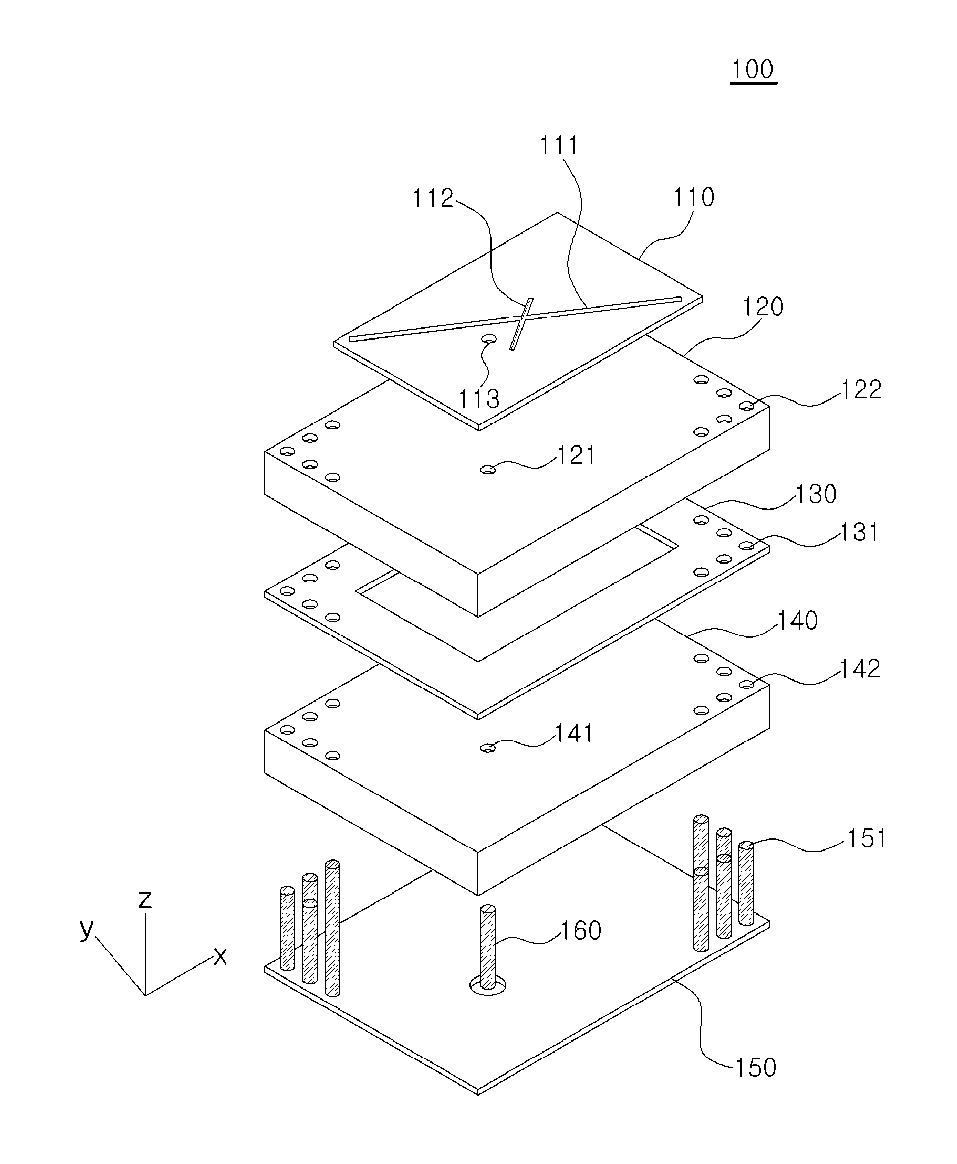
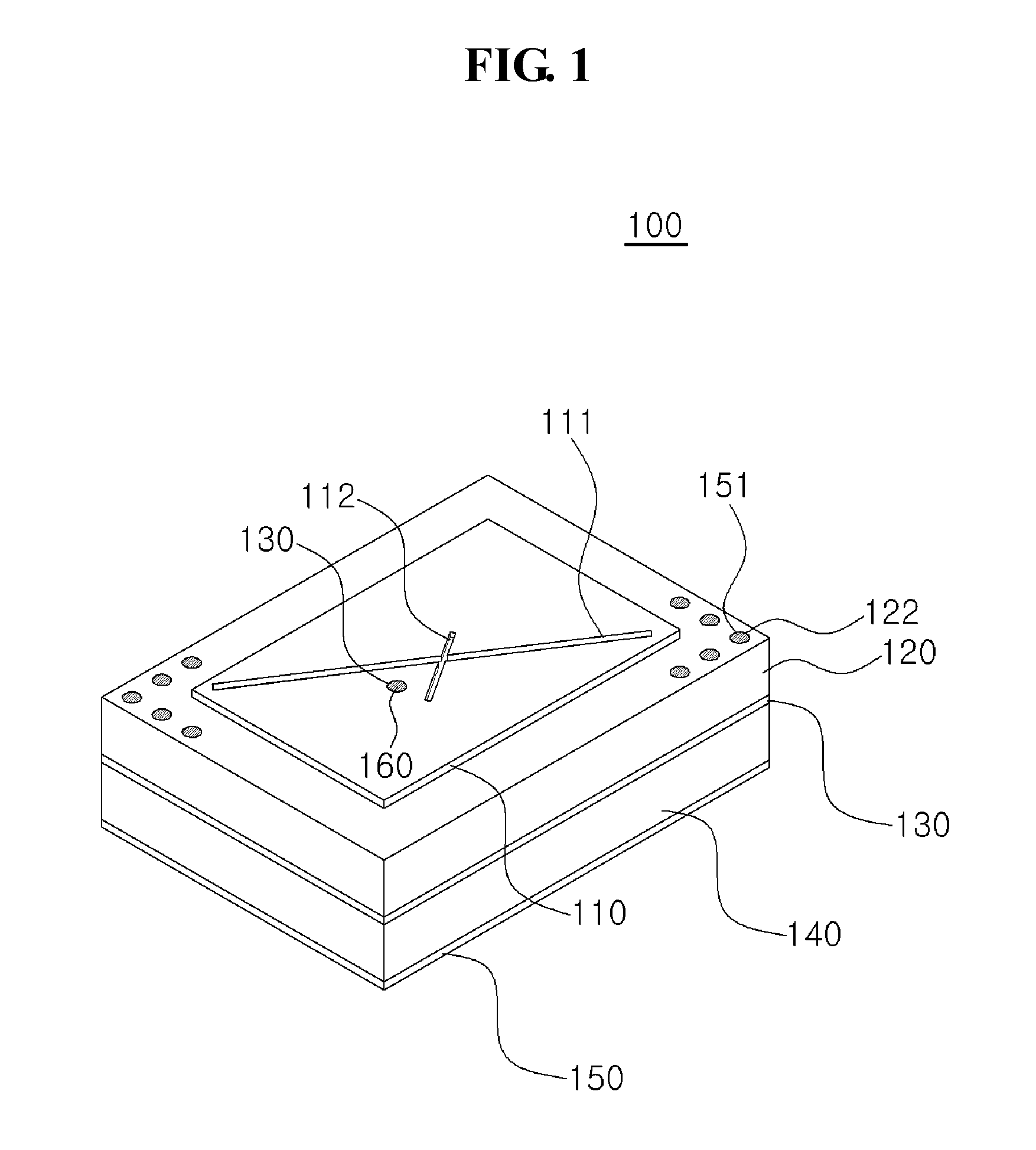
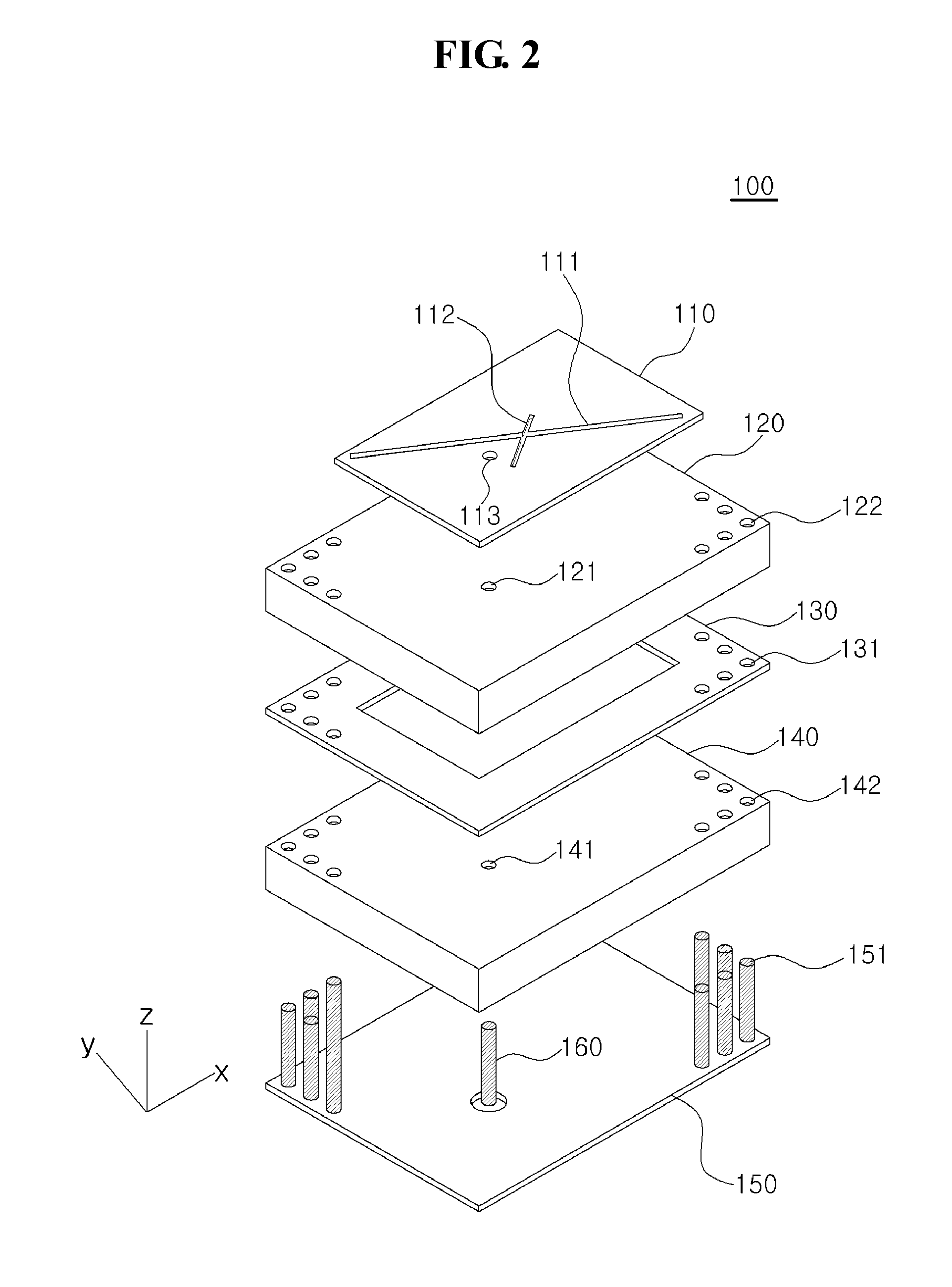
[0030]FIG. 1 is a drawing illustrating the perspective view of a patch antenna according to an embodiment of the present invention and FIG. 2 is a drawing illustrating the exploded perspective view of a patch antenna according to an embodiment of the present invention.

[0031]R...


PUM


Abstract

A patch antenna is disclosed. The disclosed patch antenna may include: a first radiator configured to generate a circular polarized wave; a first dielectric substrate equipped under the first radiator; a second radiator, placed under the first radiator at a designated distance from the first radiator, and configured to generate a linear polarized wave; a second dielectric substrate equipped under the second radiator; and a reflecting plate equipped under the second radiator at a designated distance from the second radiator; where the first dielectric substrate, the second radiator, the second dielectric substrate, and the reflecting plate are connected through at least one via. A patch antenna according to the present invention has the advantages of being able to generate linear polarized waves and circular polarized waves simultaneously, and of having a small size while still having a high design frequency band.

Description

CROSS-REFERENCE TO RELATED APPLICATIONS[0001]This application claims under 35 U.S.C. §119(a) the benefit of Korean Application No. 10-2010-0073704 filed Jul. 29, 2010, the entire contents of which are incorporated herein by reference.TECHNICAL FIELD[0002]The present invention relates to a patch antenna, more particularly to a patch antenna configured to generate both linearly polarized waves and circular polarized waves simultaneously.BACKGROUND ART[0003]With advances in wireless communication technology, it has become possible to popularize information communication terminals such as mobile telephones, PDA's, GPS receivers, etc. In such information communication terminals, small-size, light-weight, thin and flat patch antennae are mainly used.[0004]In general, the size of a patch antenna is proportionate to design frequency. Consequently, in order to produce a patch antenna that is able to generate polarized waves of the same frequency band and that is of a smaller size, a dielectr...

Claims


Application Information

Patent Timeline
Patent Type & Authority Patents(United States)
IPC IPC(8): H01Q1/38
CPCH01Q9/0414H01Q9/0421H01Q9/0428H01Q13/10H01Q19/10
Inventor YOO, TAE-HWANKIM, BYOUNG-NAM
Owner ACE TECH
Why Eureka
Try Eureka