Vehicle auxiliary hydraulic system

a technology of auxiliary hydraulic system and vehicle, which is applied in the direction of underwater vessels, special data processing applications, and non-deflectable wheel steering, etc., can solve the problems of inability to achieve proportional flow, inability to adjust the output shaft speed proportionally with the engine speed of the vehicle, and high cost of the associated hydraulic system. , to achieve the effect of quick installation and low cos

Active Publication Date: 2013-11-19
MULTIMATIC INC
View PDF14 Cites 6 Cited by
  • Summary
  • Abstract
  • Description
  • Claims
  • Application Information

AI Technical Summary

Benefits of technology

[0010]Accordingly, it would be advantageous to provide an on-board, integrated, auxiliary hydraulic system for vehicles, in particular pick-up trucks of weight classifications one or two, that utilizes the vehicle's primary internal combustion engine as the power source and is capable of providing hydraulic fluid, under pressure, to a number of access points around the vehicle. Additionally, it would be a significant advantage over the existing art to provide operator commanded fully proportional hydraulic flow at each of the access points without the requirement of internal or external proportional control valves. Another major advantage would be realized if the auxiliary hydraulic system could automatically control the proportional hydraulic flow in response to an operator demand or alternatively, a varying system generated demand independent of the speed of the primary internal combustion engine. A further advantage over the existing art would be realized by utilizing a unique pump that consumes negligible power during zero demand conditions, thereby eliminating the requirement of decoupling from the engine when the auxiliary hydraulic system is not in use.
[0011]The present invention provides such an auxiliary hydraulic system and in a principal aspect comprises an engine driven multi-piston fluid pump with electrically selectable poppet valves, as described in U.S. Pat. No. 5,190,446 to Salter et al. and U.S. Pat. No. 5,259,738 to Salter et al.; an associated microprocessor control that facilitates variable output of the fluid pump; a switchable valve arrangement to control hydraulic flow direction; an arrangement of fluid distribution pipes attached to the vehicle that terminate in detachable couplings at a number of predetermined access points; a simple user interface module adapted to command the microprocessor control from either within or in close proximity to the vehicle; wherein a range of different auxiliary equipment can be quickly and simply connected to the system and supplied with hydraulic fluid under pressure with fully controlled proportional flow.
[0012]In a principal aspect of the present invention, the multi-piston fluid pump is as described in U.S. Pat. No. 5,190,446 and U.S. Pat. No. 5,259,738 and is configured with three or more radial cylinders, each cylinder containing an electrically selectable poppet valve on the inlet, low pressure manifold side of the pump. By configuring the electrically selectable poppet valves to be normally open and then selectively closing them with an electrical signal during the cylinder's delivery stroke, variable stepped changes in the displacement of the pump can be achieved. The microprocessor control provides real time control of the electrically selectable poppet valves therefore allowing the advantage of a fully proportional flow without the requirement of complex proportional control valves. Another major advantage of this pump arrangement over the prior art is that the selective displacement approach is highly efficient and very little power is required for non-demanded capacity. This feature allows the pump to be directly driven by the vehicle's engine with no requirement for a clutch or similar decoupling arrangement.

Problems solved by technology

It is less common for road going vehicles to include an auxiliary hydraulic system since the integrated hydraulic pumps required for hydrostatic drive and other primary demands are not available.
The lack of a primary demand system dictates the usage of a dedicated auxiliary pump which can be either engine driven or incorporated in a self-contained, electric motor driven module.
Unless a piece of auxiliary equipment which requires hydraulic supply, such as a snow plow or dump box, has been installed, the associated cost of an auxiliary hydraulic system has been generally deemed to be prohibitive.
Therefore, road going, general purpose, light and medium duty pick-up trucks of weight classifications one or two do not generally include auxiliary hydraulic systems even as a customer purchased option.
In the case of a snow plow the hydraulic supply represents half of the total system cost.
However, although simplistic, the Miceli prior art still requires an electric motor-driven pump, selector valve, angle control valve, plow-lowering valve, reservoir tank and associated valve solenoids in addition to the plow, mounting structure and hydraulic cylinders.
These poppet valves provide on-off control and direction switching but have no proportional flow capability as applications such as snow plows can operate adequately without velocity control.
Again, because of the prohibitive costs associated with mechanical power take off, road going, general purpose, light and medium duty pick-up trucks of weight classifications one or two do not generally include this type of capability although a number of aftermarket manufacturers do offer some limited compatibility units.
A major disadvantage of these power take off units is that their output shaft speed varies proportionally with the vehicle's engine speed.
In either case, a large collection of utility equipment tends to result in a large number of associated prime movers with all of the associated maintenance demands such as oil and air filter changes.
In the majority of non-industrial applications, as around the home, these prime movers tend to be subjected to relatively low usage, resulting in an extremely poor value proposition.

Method used


Image

  • Vehicle auxiliary hydraulic system
  • Vehicle auxiliary hydraulic system
  • Vehicle auxiliary hydraulic system

Examples


Embodiment Construction

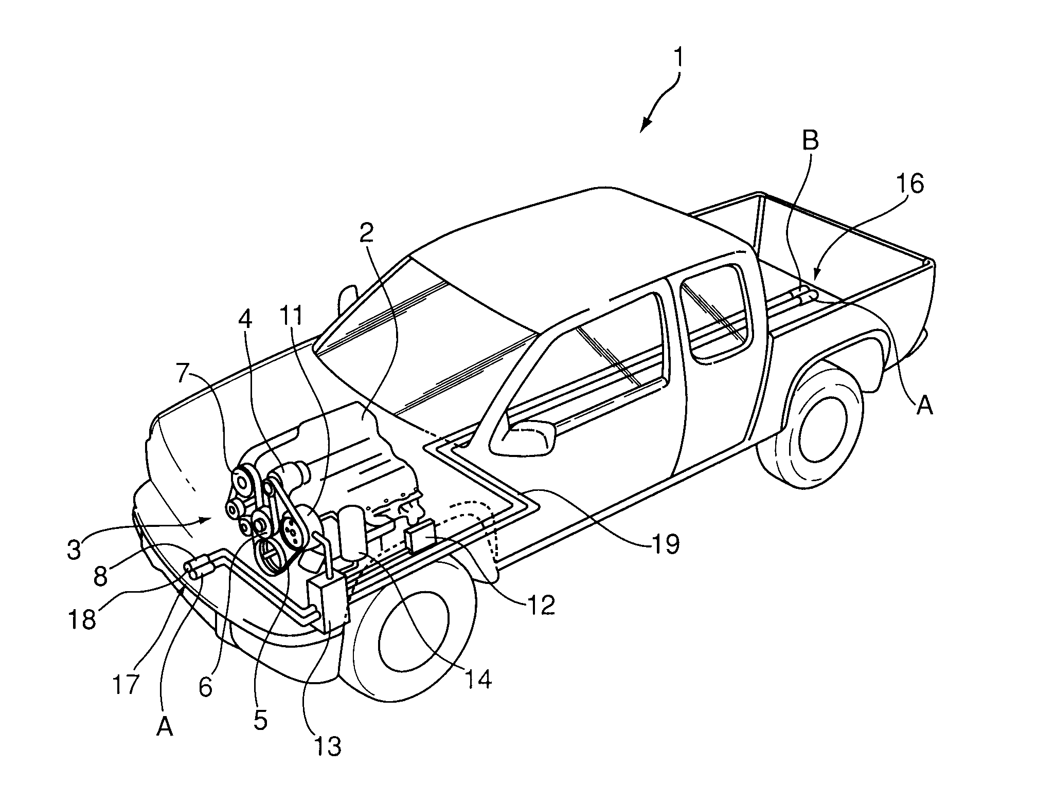
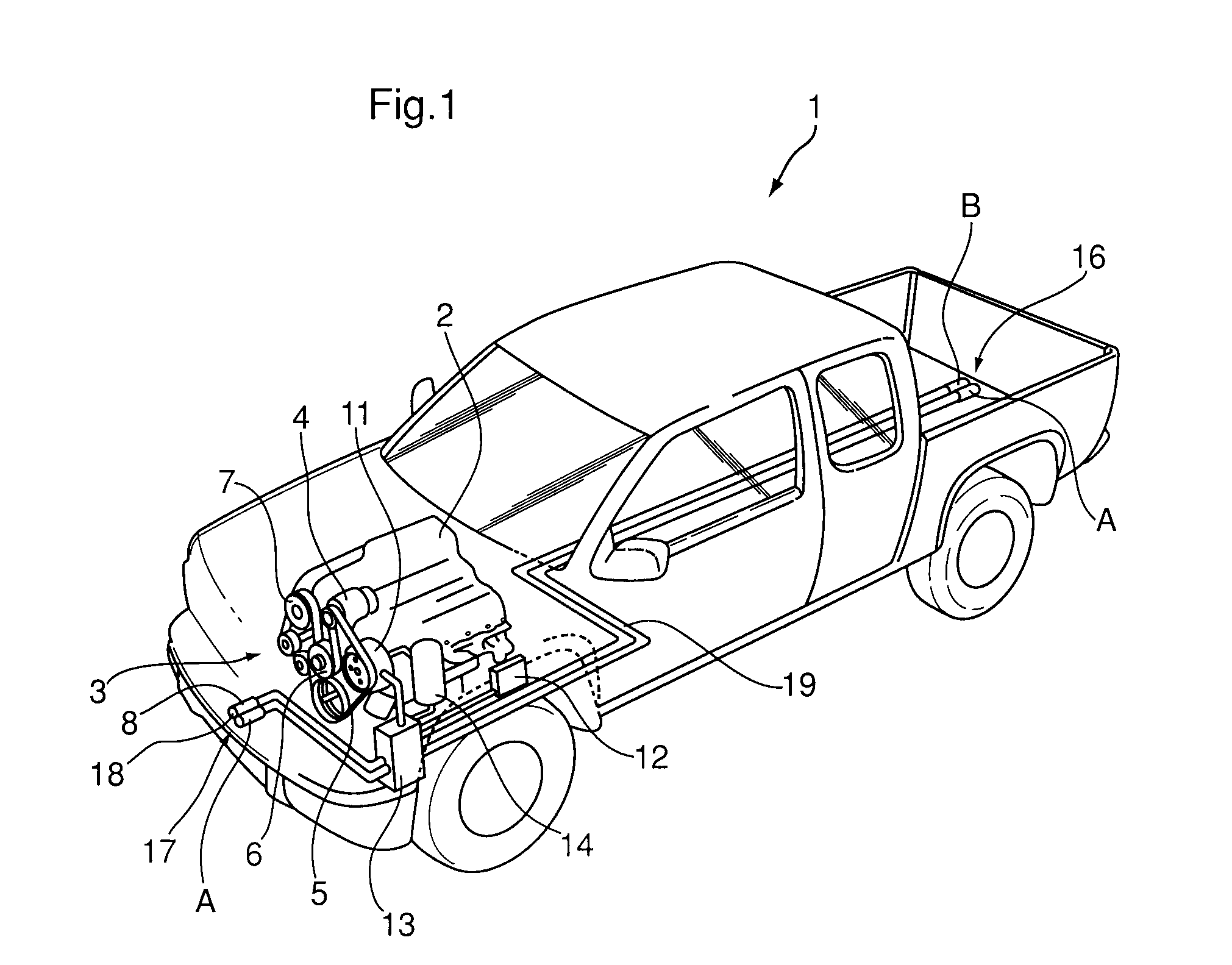
[0031]Referring to FIG. 1, a pick-up truck (1) of weight class one or two is conventionally powered by an internal combustion engine (2). The internal combustion engine (2) is configured with a front end accessory drive (FEAD) (3) consisting of a multi-grooved serpentine belt (5) arranged to drive a number of conventional ancillary components such as an alternator (4), water pump (6) and air conditioning compressor (7). The FEAD is additionally configured to drive a multi-piston fluid pump (11) capable of delivering hydraulic fluid under pressure. The multi-piston fluid pump (11) contains electrically selectable poppet valves configured to facilitate variable output. The electrically selectable poppet valves are powered via a microprocessor control (12) so that predetermined proportional hydraulic flow is supplied to a distribution valve block (13) by the multi-piston fluid pump (11). A reservoir (14) is connected so as to supply the pump with an adequate volume of hydraulic fluid a...


PUM


Abstract

An auxiliary hydraulic system for vehicles, in particular pick-up trucks, is configured to supply hydraulic fluid under pressure to both on-board and off-board auxiliary equipment such as snow plows, dump boxes and wood splitters. The auxiliary hydraulic system includes a multi-piston fluid pump with electrically selectable poppet valves and an associated microprocessor control that facilitates variable output so that a desired proportional flow can be supplied to the auxiliary equipment. The system also provides a switchable valve arrangement for directional control and an arrangement of fluid distribution pipes and detachable couplings so that a range of different auxiliary equipment can be quickly and simply connected to the system. A simple user interface is also included so that the operator can command the auxiliary equipment from either within or in close proximity to the vehicle.

Description

RELATED APPLICATIONS[0001]This application is a 35 U.S.C. 371 national stage filing from International Application No. PCT / CA2009 / 000392 filed Apr. 1, 2009, which claims priority to Canadian Patent Application No. 2,630,199, filed May 1, 2008, the teachings of which are incorporated herein by reference.FIELD OF THE INVENTION[0002]This invention relates to an auxiliary hydraulic system for vehicles, in particular light and medium duty pick-up trucks of weight classifications one or two, that is configured to supply hydraulic fluid to both on-board and off-board auxiliary equipment using a unique microprocessor controlled multi-piston fluid pump.BACKGROUND OF THE INVENTION[0003]On-board auxiliary hydraulic systems for work vehicles are well known in the art with agricultural equipment such as tractors and construction equipment such as excavators typically providing fully integrated arrangements. These integrated auxiliary hydraulic systems can be supplied either by the work vehicle's...

Claims


Application Information

Patent Timeline
Patent Type & Authority Patents(United States)
IPC IPC(8): A01B69/00
CPCA01D69/03B60K25/02
Inventor HOLT, LAURENCE JLAVOIE, PAUL
Owner MULTIMATIC INC
Why Eureka
Try Eureka