Wind turbine braking device and method of use damping drivetrain oscillation

a technology of wind turbines and damping devices, which is applied in the direction of rotors, electric generator control, vessel construction, etc., can solve the problems of automatic vibration (i.e. torsional oscillation), affecting the efficiency of wind turbine braking, etc., to achieve the effect of increasing damping efficiency and greater effect accuracy

Inactive Publication Date: 2013-11-26
SIEMENS AG
View PDF13 Cites 7 Cited by
  • Summary
  • Abstract
  • Description
  • Claims
  • Application Information

AI Technical Summary

Benefits of technology

[0013]Against this background, the present invention addresses the problem of providing an improved means of oscillation damping, which preferably involves in particular at most modest additional installation or maintenance effort and / or preferably results in increased damping efficiency, preferably in particular offering greater accuracy of effect, in comparison with purely passive oscillation damping.

Problems solved by technology

Due to the transmission of force from the rotor to the generator and due to further influences (see below), the drive train and the wind turbine components surrounding it are exposed to a multiplicity of forces, which result in oscillations, i.e. vibrations in the drive train.
Firstly, external factors such as e.g. the wind speed, the wind direction, the external temperature or turbulence play a role. These factors of influence exert forces on the rotor, not all of which act in an axial direction of the drive train or the axis of the rotor. This results in mainly low-frequency oscillations of up to approximately 10 Hz in the drive train.
Secondly, a complex overall system consisting of numerous mechanically-interconnected components works during operation of the wind turbine. For example, provision is often made for a speed-transforming gear which transforms the relatively slow rotation of the rotor or a first shaft of the drive train into a faster rotation of a second shaft of the drive train. Vibrations (i.e. torsional oscillations) automatically occur in this gear due to the connection of the two drive train components by means of toothed gearwheels or other elements for the transmission of force. Torsional forces are also transmitted from the gear onto the machine housing, i.e. onto the internal structure of the cabin. Moreover, the gear also produces axial oscillations, mainly in the high-frequency range above 10 Hz.
Thirdly, pitch and yawing moments are produced by constraining forces in connections between the cabin and components that are mounted in the cabin. These constraining forces occur as a result of the assembly, as a result of weight distribution, and due to excitation of the natural frequencies of the drive train. The pitch and yawing moments in the drive train produce forces which act on the subfloor in the cabin of the wind turbine and can damage this. The natural frequency of an individual component is dependent on its weight and / or its inertia in this case. By combining a system of components during the assembly, new system characteristics and hence new natural frequencies are produced.
This coupling can also cause oscillations during operation.
The oscillations and force effects in the region of the drive train as summarized here in the form of an overview represent a problem during operation of the wind turbine, because they can significantly reduce the service life of the wind turbine as a whole, or individual components thereof, and / or permanently jeopardize their functionality.
In particular, high frequency oscillations above approximately 10 Hz can cause significant damage at high amplitudes, primarily in the gear, in the generator and to the cabin of the wind turbine.
However, such active damping components require additional structural space within the cabin of the wind turbine, as well as being expensive to provide and maintenance-intensive.
Control of the converter for the purpose of oscillation damping is therefore possible and is currently also realized; however, it reduces the efficiency of the energy production and also introduces an additional factor of influence into the control of the converter.

Method used


Image

  • Wind turbine braking device and method of use damping drivetrain oscillation
  • Wind turbine braking device and method of use damping drivetrain oscillation
  • Wind turbine braking device and method of use damping drivetrain oscillation

Examples


Embodiment Construction

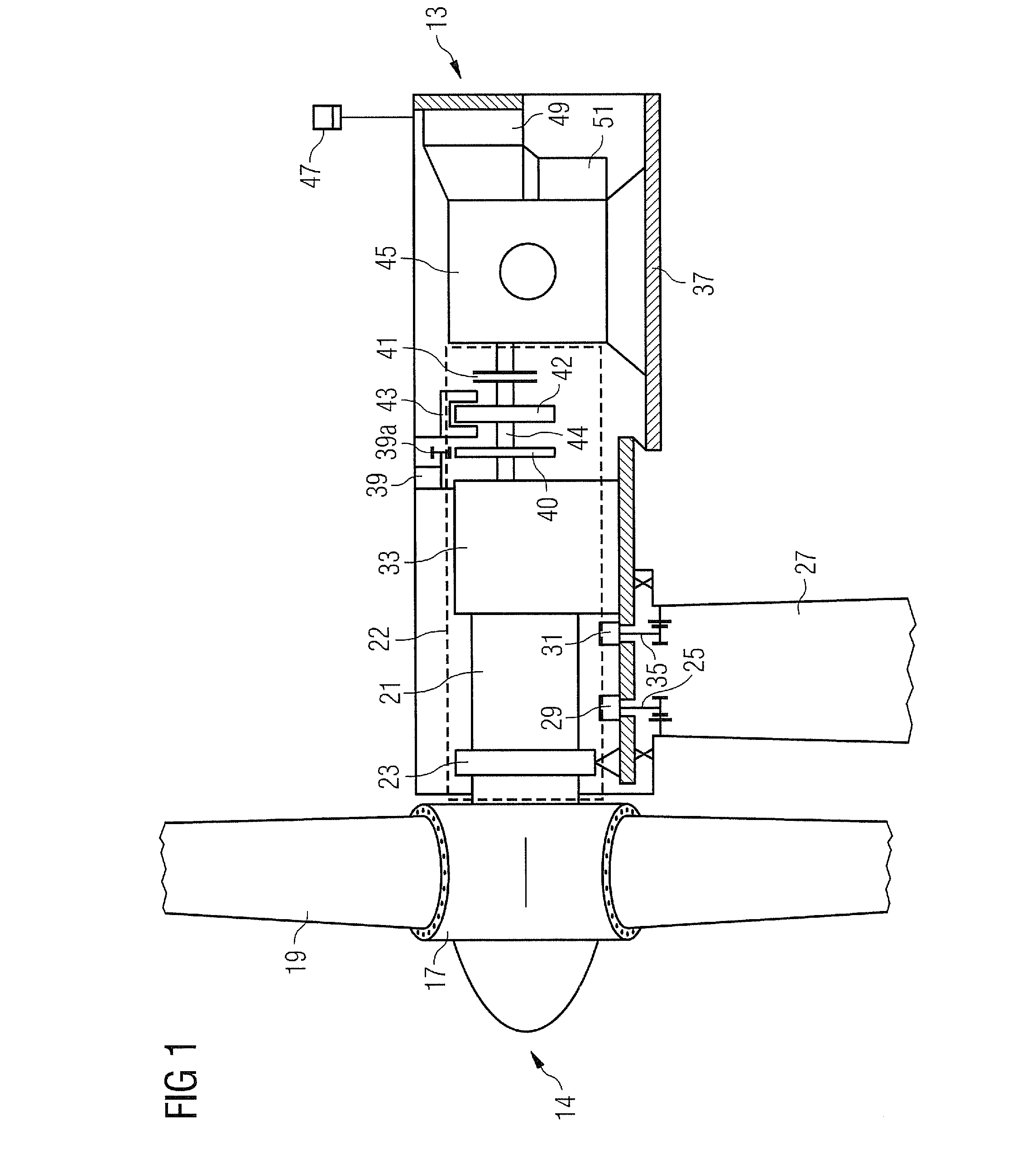
[0070]FIG. 1 shows a wind turbine 13 according to an embodiment of the invention. On its front side, which faces the wind, it features a rotor 14 comprising a plurality of rotor blades 19. These are connected to a hub 17. A first shaft 21 leads from the hub 17 into the interior of the cabin 37 of the wind turbine 13. Said first shaft is mounted in the cabin 37 via an elastic main mounting 23 and a first yoke 25 and a second yoke 35 (whose positions can be adjusted by means of motors 29, 31).

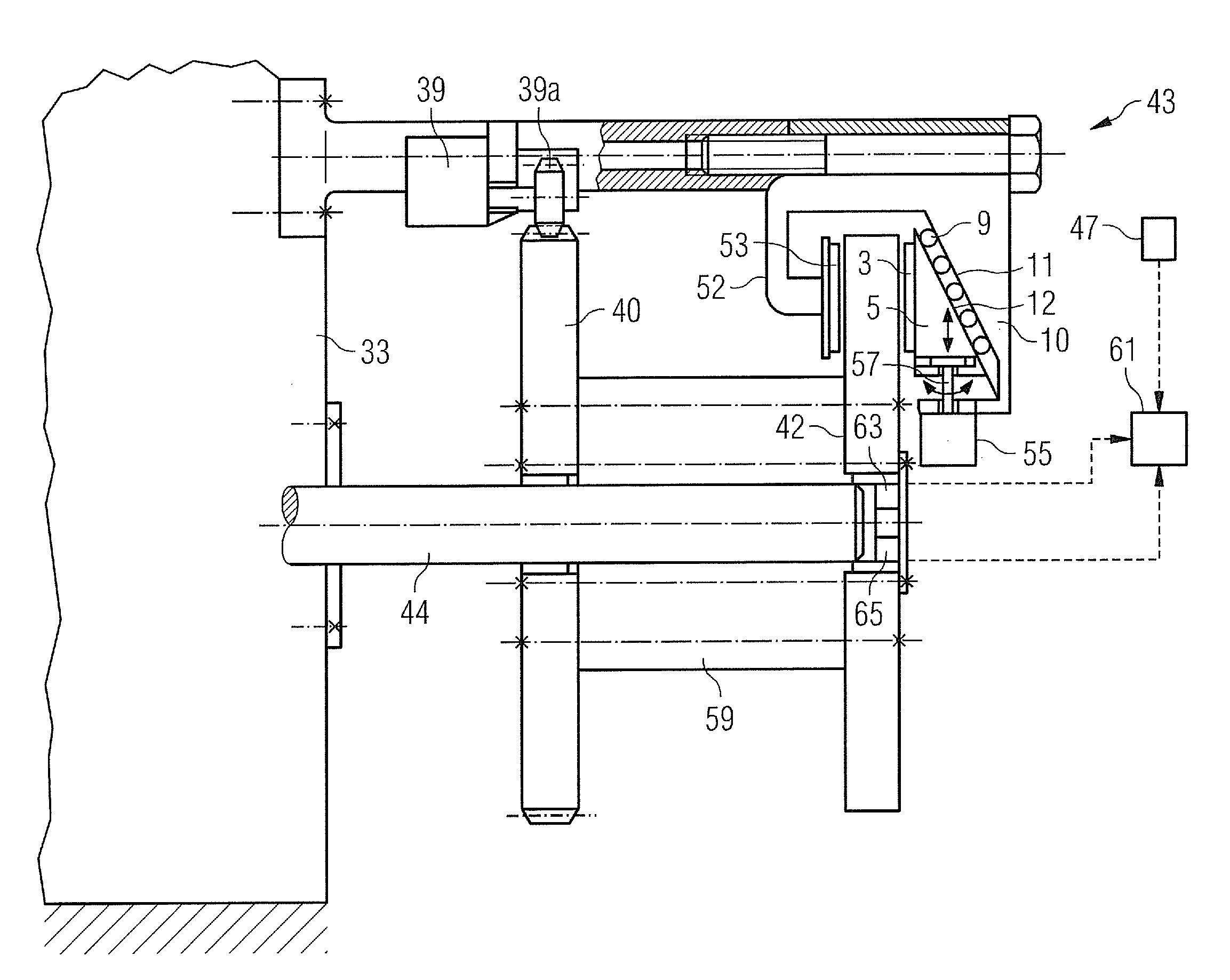
[0071]A gear 33 converts the rotation of the first shaft 21 into a rotation of a second shaft 44, wherein the second shaft 44 is arranged on that side of the gear 33 which faces away from the second shaft 21. The second shaft 44 leads to a generator 45, in which current is obtained from the rotational energy of the second shaft 44. A coupling 41 is used to couple the second shaft 44 in or out, in order that in hazardous situations the generator 45 can be decoupled from the rotation of the second ...


PUM


Abstract

A method for the oscillation damping of a drive train in a wind turbine is proposed. The drive train connects a rotor to a generator. Parameter values representing an oscillation of the drive train are calculated and, on the basis of the calculated parameter values, damping forces which counteract the oscillation of the drive train are exerted in a controlled manner on the drive train by a braking device.

Description

CROSS REFERENCE TO RELATED APPLICATIONS[0001]This application claims priority of European Patent Office application No. 11151847.8 filed Jan. 24, 2011, which is incorporated by reference herein in its entirety.FIELD OF INVENTION[0002]The present invention relates to a method for the oscillation damping of a drive train in a wind turbine, which drive train connects a rotor to a generator. It further relates to such a wind turbine and to the specific use of a braking device in such a wind turbine.BACKGROUND OF INVENTION[0003]In a wind turbine the kinetic energy of the wind is used for the purpose of producing rotational movement in a rotor. This rotational movement is transmitted via a drive train to a generator which generates electrical energy from the rotational energy.[0004]Due to the transmission of force from the rotor to the generator and due to further influences (see below), the drive train and the wind turbine components surrounding it are exposed to a multiplicity of forces...

Claims


Application Information

Patent Timeline
Patent Type & Authority Patents(United States)
IPC IPC(8): F03D7/02
CPCF03D7/0248F03D11/02F05B2260/96Y02E10/722Y02E10/723F03D15/00F03D15/10F03D80/60Y02E10/72F03D7/0244F03D7/0296F05B2260/962
Inventor WOHLLEB, MATTHIAS
Owner SIEMENS AG
Why Eureka
Try Eureka