Two dimension layout and point transfer system

a two-dimensional layout and point transfer technology, applied in the field of two-dimensional layout systems, can solve the problems of missing the mark, overly complex and expensive previous laser based systems, and inability to use conventional gps inside standard steel construction buildings

Active Publication Date: 2013-12-03
SPECTRA PRECISION (USA) LLC
View PDF28 Cites 19 Cited by
  • Summary
  • Abstract
  • Description
  • Claims
  • Application Information

AI Technical Summary

Benefits of technology

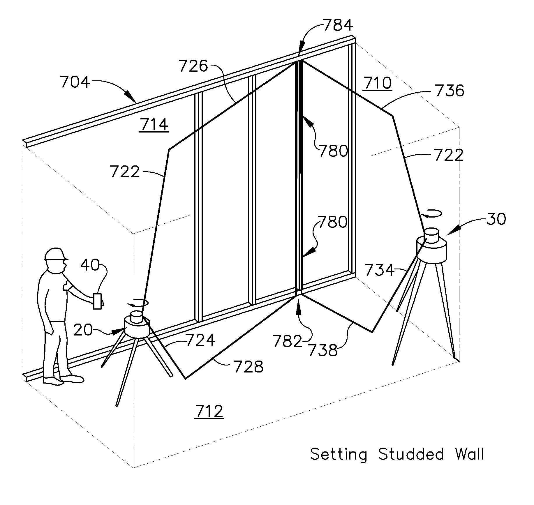
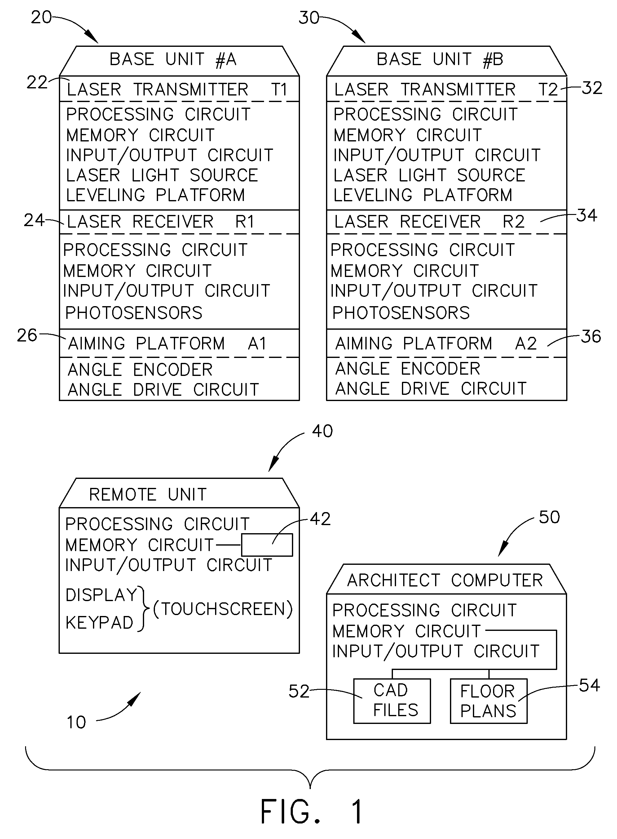
[0010]Accordingly, it is an advantage to provide a floor layout system that includes two base units that can have an alignment axis established therebetween, and a remote unit that communicates with both of the base units, in which the system is configured to provide a to visual presentation of virtual points on a jobsite physical surface that have predetermined coordinates, relative to locations of at least two benchmark points.

Problems solved by technology

Conventional GPS is not usable inside standard steel construction buildings.
Previous laser based systems have been overly complex and expensive, missing the mark in almost every area required for this market.
The complexity of this method is very high, and the requirement of having constant rotational laser scanning is critical.
In addition, it is computationally intensive, especially when setting up the system.
Job site obstructions also become a challenge when acquiring sufficient targets in the right place, with respect to the position of the transmitter, to provide a strong calculation of position.
Constant rotation speed is again very critical, and the position calculation for this method typically has not been sufficient accuracy for what is required for typical construction jobsite layout.
Otherwise serious errors can occur, and become increasingly large as the incident projection angle onto the surface becomes steeper.

Method used


Image

  • Two dimension layout and point transfer system
  • Two dimension layout and point transfer system
  • Two dimension layout and point transfer system

Examples


Embodiment Construction

[0037]Reference will now be made in detail to the present preferred embodiment, an example of which is illustrated in the accompanying drawings, wherein like numerals indicate the same elements throughout the views.

[0038]It is to be understood that the technology disclosed herein is not limited in its application to the details of construction and the arrangement of components set forth in the following description or illustrated in the drawings. The technology disclosed herein is capable of other embodiments and of being practiced or of being carried out in various ways. Also, it is to be understood that the phraseology and terminology used herein is for the purpose of description and should not be regarded as limiting. The use of “including,”“comprising,” or “having” and variations thereof herein is meant to encompass the items listed thereafter and equivalents thereof as well as additional items. Unless limited otherwise, the terms “connected,”“coupled,” and “mounted,” and variat...


PUM


Abstract

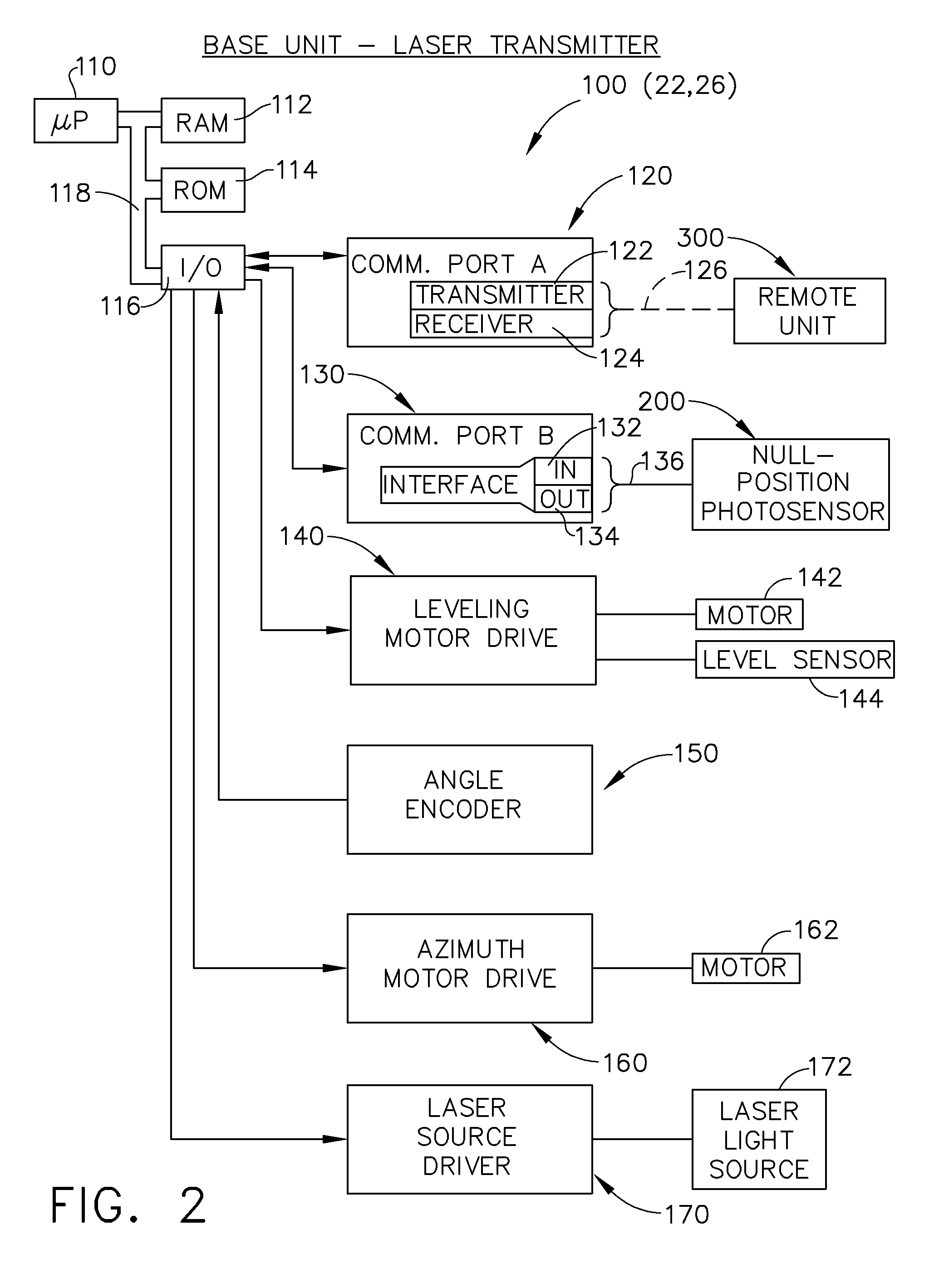
A two-dimension layout system identifies points and their coordinates, and transfers identified points on a solid surface to other surfaces in a vertical direction. Two leveling laser light transmitters are used with a remote unit to control certain functions. The laser transmitters rotate about the azimuth, and emit vertical (plumb) laser planes. After being set up using benchmark points, the projected lines of the laser planes will intersect on the floor of a jobsite at any point of interest in a virtual floor plan, under control of a user with the remote unit. The laser light planes also project lines that will intersect along the ceiling at a point that is truly plumb above the crossing point on the floor. The laser planes also provide an “implied” plumb line that is projected in space, which is visible along a solid vertical surface between the intersecting floor and ceiling points.

Description

CROSS-REFERENCE TO RELATED APPLICATIONS[0001]The present application is a continuation of application Ser. No. 13 / 287,028, titled “TWO DIMENSION LAYOUT AND POINT TRANSFER SYSTEM,” filed on Nov. 1, 2011, now U.S. Pat. No. 8,281,495, which is a continuation of application Ser. No. 12 / 824,716, titled “TWO DIMENSION LAYOUT AND POINT TRANSFER SYSTEM,” filed on Jun. 28, 2010, now U.S. Pat. No. 8,087,176.TECHNICAL FIELD[0002]The technology disclosed herein relates generally to layout “surveying” equipment and is particularly directed to a two-dimension layout system of the type which identifies points and their coordinates, and transfers identified points on a surface to other surfaces in a vertical direction. Embodiments are specifically disclosed using two laser light transmitters with a remote unit to control certain functions. The laser transmitters may be identical. Preferably the laser transmitters include a self-leveling capability, and exhibit a rotation about the azimuth, and a ve...

Claims


Application Information

Patent Timeline
Patent Type & Authority Patents(United States)
IPC IPC(8): G01C15/02G01B11/27
CPCG01C15/004
Inventor HAYES, JAMES N.SNYDER, CHRIS W.
Owner SPECTRA PRECISION (USA) LLC
Why Eureka
Try Eureka