Turbine rotor
a turbine rotor and rotor body technology, applied in the field of turbine rotors, can solve the problems of difficult to produce a turbine rotor whole from ni-base alloy, high cost and effort required for providing the cooling hole, and achieve the effects of high tolerable temperature, enhanced steam temperature, and easy manufacturing
- Summary
- Abstract
- Description
- Claims
- Application Information
AI Technical Summary
Benefits of technology
Problems solved by technology
Method used
Image
Examples
embodiment 1
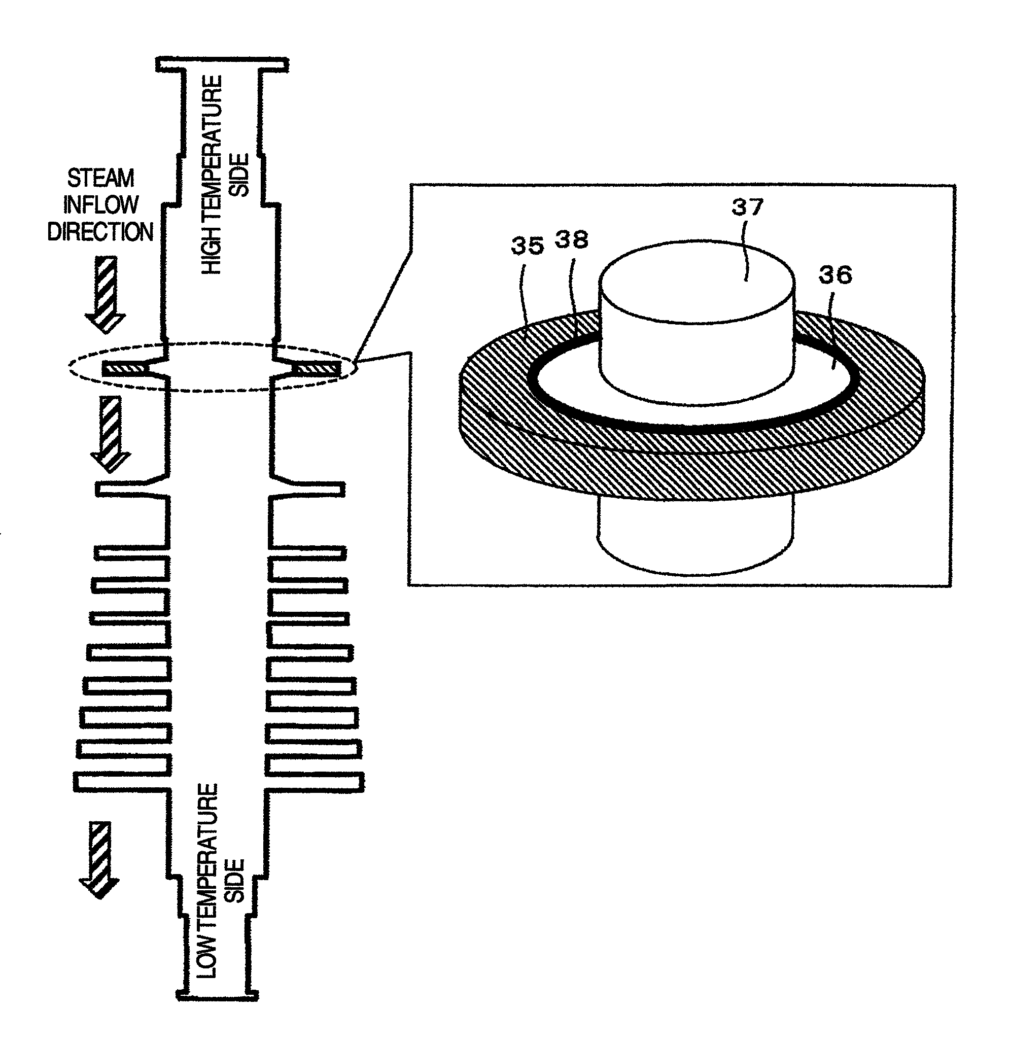
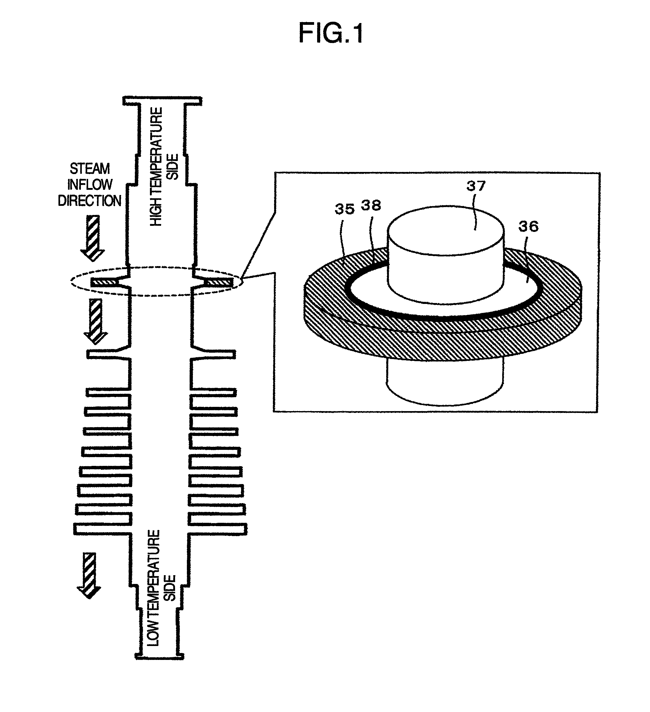
[0034]A first embodiment will be described by using FIGS. 1 to 5.
[0035]FIG. 1 is a sectional view of a turbine rotor for high pressure steam having a rotor disc. The turbine rotor includes an outer rotor disc 35, an inner rotor disc 36, and a rotor shaft 37, and the outer rotor disc 35 and the inner rotor disc 36 are fastened by welding via a weld metal 38, and are integrated. A structure such as a fixing groove for fastening a rotor blade is provided on an outer circumferential side of the rotor disc.
[0036]In the present embodiment, because the outer rotor disc 35 requires high temperature strength, an Ni-base alloy material is used therefor. The inner rotor disc 36 does not require such high temperature strength as the outer side, and therefore, less expensive 12Cr steel (high chrome steel) is used therefor. In the present embodiment, the inner rotor disc is formed by 12Cr steel integrally with the rotor shaft 37. The weld metal 38 can be selected in accordance with the temperatur...
embodiment 2
[0044]By using FIGS. 6 to 11, a second embodiment will be described. FIG. 6 is a sectional view of a turbine rotor for high-pressure steam according to the present embodiment. In the present embodiment, as shown in FIG. 6, the outer rotor disc 35 is provided with cooling holes 39 which penetrate the disc in the axial direction of the rotor shaft. The other parts are the same as those in embodiment 1. Therefore, the detailed description will be omitted, and only the difference will be described.
[0045]FIG. 7 shows one example of a process flow of welding the outer rotor disc 35 to the inner rotor disc 36 in the turbine rotor according to the present embodiment. First, in step 201, processing for introducing the cooling holes 39 into the outer disc 35 is performed. Next, in step 202, the outer rotor disc 35 is mounted on the rotor disc 36. Thereafter, when the instructions to start the welding process is issued in step 203, the rotor is preheated in order to alleviate the thermal stres...
embodiment 3
[0051]Concerning a third embodiment, the shape and arrangement of openings of cooling holes will be described by using FIGS. 11 and 12. In embodiment 2, described is the example showing that the through-holes which are arranged in a row in the circumferential direction and have a circular section are provided. The present embodiment differs from embodiment 2 in respect only of the shape of the cooling hole 39, and is the same as the embodiment 2 in the other respects. Therefore, the description thereof will be partially omitted.
[0052]FIG. 11 shows one example of the shape and arrangement of the cooling holes 39. By forming the shape of the cooling hole 39 to be circular, stress concentration can be avoided. By making the sizes of the cooling holes 39 constant (uniform), variation of the cooling efficiency can be suppressed. Further, in order to cool the rotor disc efficiently and uniformly in the circumferential direction, the cooling holes 39 are arranged in a straight line in the ...
PUM
 Abstract
Description
Claims
Application Information
 - R&D
- Intellectual Property
- Life Sciences
- Materials
- Tech Scout
- Unparalleled Data Quality
- Higher Quality Content
- 60% Fewer Hallucinations
Browse by: Latest US Patents, China's latest patents, Technical Efficacy Thesaurus, Application Domain, Technology Topic, Popular Technical Reports.
© 2025 PatSnap. All rights reserved.Legal|Privacy policy|Modern Slavery Act Transparency Statement|Sitemap|About US| Contact US: help@patsnap.com


