Turbine rotor

a turbine rotor and rotor body technology, applied in the direction of machines/engines, mechanical equipment, liquid fuel engines, etc., can solve the problems of difficult to produce large steel ingots, difficult to produce a turbine rotor whole from ni-base alloy, and high effort and cost for providing the cooling hole, etc., to achieve the effect of high tolerable temperature, easy manufacturing, and enhanced steam temperatur

Inactive Publication Date: 2010-12-30
MITSUBISHI HITACHIPOWER SYST LTD
View PDF14 Cites 11 Cited by
  • Summary
  • Abstract
  • Description
  • Claims
  • Application Information

AI Technical Summary

Benefits of technology

[0012]As described above, the turbine rotor with a high tolerable temperature and capable of being easily manufactured can be provided. Further, the turbine rotor can cope with enhancement in steam temperature, and therefore contributes to enhancement in efficiency of a steam turbine power plant.

Problems solved by technology

Since the axial length of the rotor shaft measures several meters, much effort and cost are required for providing the cooling hole.
Further, although the tolerable temperature of a Ni-base alloy is high, it is the material from which production of large steel ingots is difficult.
Therefore, it is difficult to produce a turbine rotor entire from the Ni-base alloy.
Further, the Ni-base alloy has the problem that the cost is high.

Method used


Image

  • Turbine rotor
  • Turbine rotor
  • Turbine rotor

Examples


embodiment 1

[0034]A first embodiment will be described by using FIGS. 1 to 5.

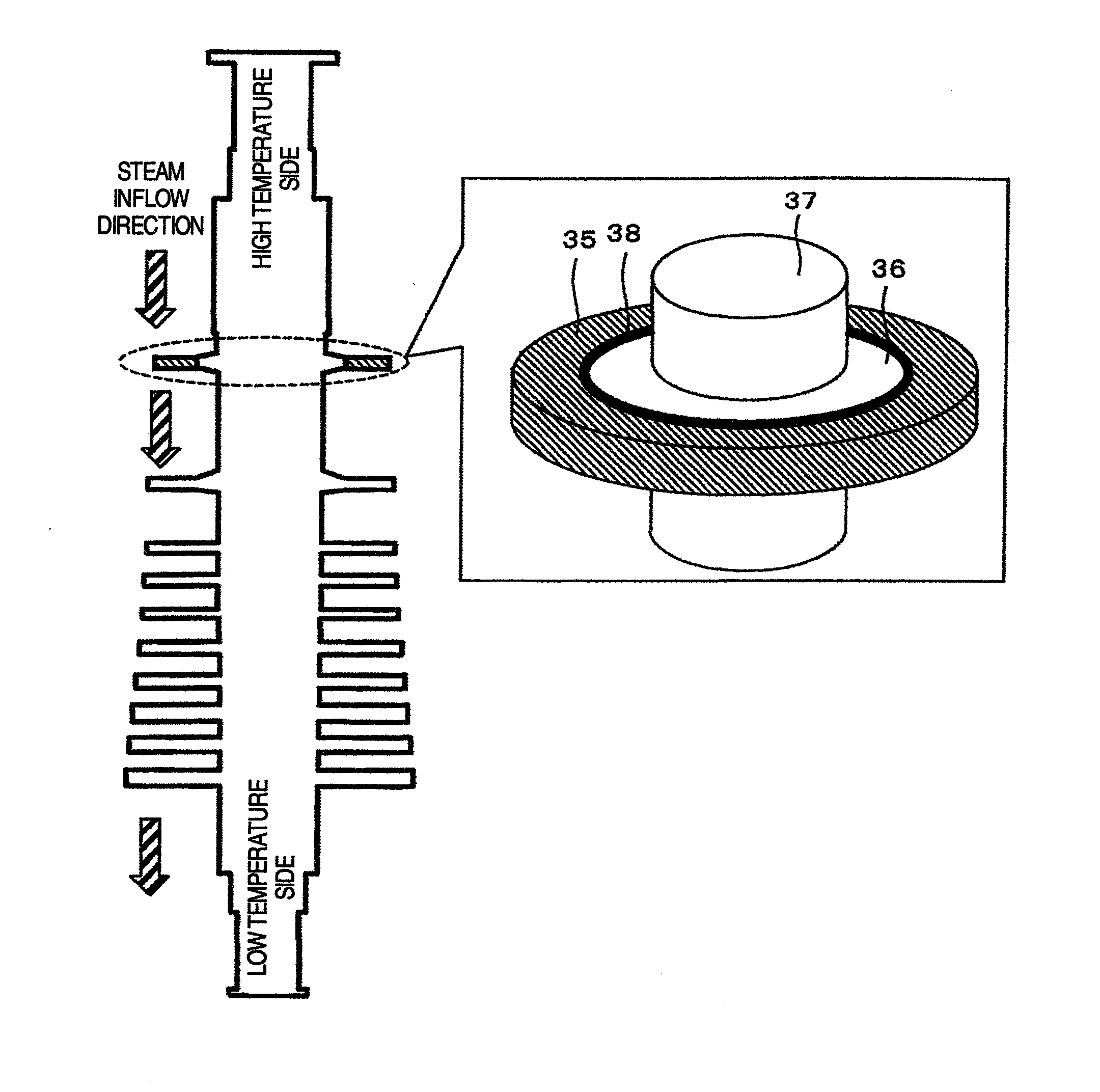
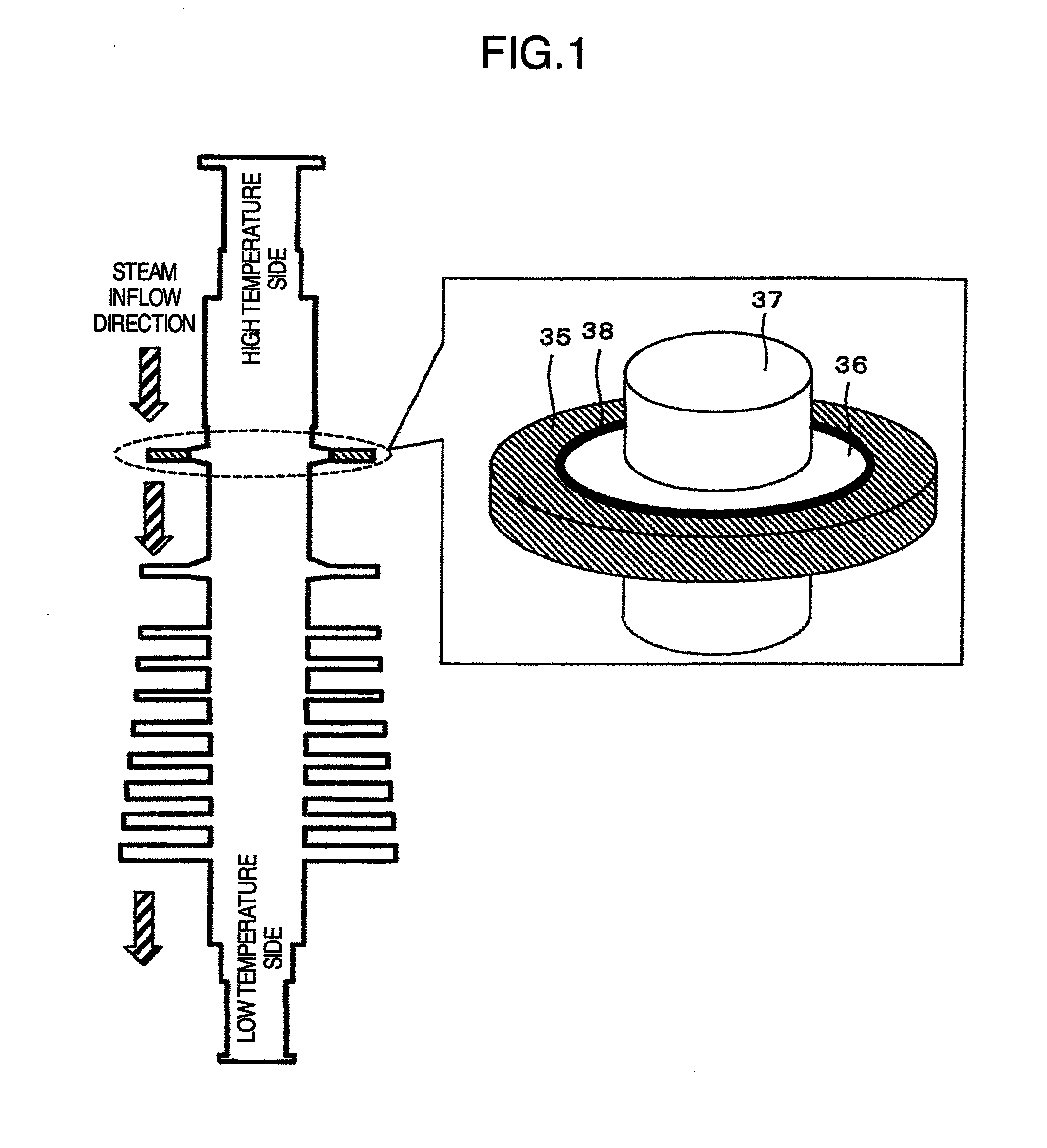
[0035]FIG. 1 is a sectional view of a turbine rotor for high pressure steam having a rotor disc. The turbine rotor includes an outer rotor disc 35, an inner rotor disc 36, and a rotor shaft 37, and the outer rotor disc 35 and the inner rotor disc 36 are fastened by welding via a weld metal 38, and are integrated. A structure such as a fixing groove for fastening a rotor blade is provided on an outer circumferential side of the rotor disc.

[0036]In the present embodiment, because the outer rotor disc 35 requires high temperature strength, an Ni-base alloy material is used therefor. The inner rotor disc 36 does not require such high temperature strength as the outer side, and therefore, less expensive 12Cr steel (high chrome steel) is used therefor. In the present embodiment, the inner rotor disc is formed by 12Cr steel integrally with the rotor shaft 37. The weld metal 38 can be selected in accordance with the temperatur...

embodiment 2

[0044]By using FIGS. 6 to 11, a second embodiment will be described. FIG. 6 is a sectional view of a turbine rotor for high-pressure steam according to the present embodiment. In the present embodiment, as shown in FIG. 6, the outer rotor disc 35 is provided with cooling holes 39 which penetrate the disc in the axial direction of the rotor shaft. The other parts are the same as those in embodiment 1. Therefore, the detailed description will be omitted, and only the difference will be described.

[0045]FIG. 7 shows one example of a process flow of welding the outer rotor disc 35 to the inner rotor disc 36 in the turbine rotor according to the present embodiment. First, in step 201, processing for introducing the cooling holes 39 into the outer disc 35 is performed. Next, in step 202, the outer rotor disc 35 is mounted on the rotor disc 36. Thereafter, when the instructions to start the welding process is issued in step 203, the rotor is preheated in order to alleviate the thermal stres...

embodiment 3

[0051]Concerning a third embodiment, the shape and arrangement of openings of cooling holes will be described by using FIGS. 11 and 12. In embodiment 2, described is the example showing that the through-holes which are arranged in a row in the circumferential direction and have a circular section are provided. The present embodiment differs from embodiment 2 in respect only of the shape of the cooling hole 39, and is the same as the embodiment 2 in the other respects. Therefore, the description thereof will be partially omitted.

[0052]FIG. 11 shows one example of the shape and arrangement of the cooling holes 39. By forming the shape of the cooling hole 39 to be circular, stress concentration can be avoided. By making the sizes of the cooling holes 39 constant (uniform), variation of the cooling efficiency can be suppressed. Further, in order to cool the rotor disc efficiently and uniformly in the circumferential direction, the cooling holes 39 are arranged in a straight line in the ...


PUM


Abstract

A turbine rotor which is easy to manufacture and has a high tolerable temperature is provided. A highly efficient steam turbine power plant is also provided. The turbine rotor is configured from a rotor shaft, an inner rotor disc constructed integrally with the rotor shaft, and an outer rotor disc which is welded to the inner rotor disc via a weld metal part and has a structure for fixing a turbine blade. The outer rotor disc preferably has a cooling hole which extends in an axial direction to penetrate the outer rotor disc over the thickness of the outer rotor disc.

Description

BACKGROUND OF THE INVENTION[0001]1. Field of the Invention[0002]The present invention relates to a turbine rotor.[0003]2. Description of Related Art[0004]Energy conservation and environmental conservation, and in particular reduction in CO2 has begun to attract growing interest, and it is desired in the field of a steam turbine power generation plant to increase the capacity and enhance the thermal efficiency. Enhancement in thermal efficiency is achieved by increasing the temperature and pressure of steam, and further increase in temperature is planed in future. The first stage blade of a high pressure turbine is the first element to be exposed to steam among rotating elements, and it is necessary to secure durability to high-temperature and high-pressure steam, and in particular to secure strength reliability, among others.[0005]In a conventional material including iron as a main component, if the main steam temperature exceeds 650° C., the high-temperature strength, in particular...

Claims


Application Information

Patent Timeline
Patent Type & Authority Applications(United States)
IPC IPC(8): F01D5/08
CPCF01D5/063F05D2230/232F05D2220/31F01D5/081
Inventor NISHIOKA, EIJIARAI, MASAHIKODOI, HIROYUKI
Owner MITSUBISHI HITACHIPOWER SYST LTD
Why Eureka
Try Eureka