Multi-axis/multi-field charged particle cancer therapy method and apparatus

a cancer therapy and multi-field technology, applied in the field of solid cancer treatment, can solve the problems of reduced ability to repair damaged dna, death of patients, and special vulnerability to attack on dna

Active Publication Date: 2013-12-03
BALAKIN ANDREY VLADIMIROVICH +1
View PDF369 Cites 27 Cited by
  • Summary
  • Abstract
  • Description
  • Claims
  • Application Information

AI Technical Summary

Problems solved by technology

These particles damage the DNA of cells, ultimately causing their death.
Cancerous cells, because of their high rate of division and their reduced ability to repair damaged DNA, are particularly vulnerable to attack on their DNA.
Residual particles are used in the accelerator without supplying new particles if sufficient charge is available.

Method used


Image

  • Multi-axis/multi-field charged particle cancer therapy method and apparatus
  • Multi-axis/multi-field charged particle cancer therapy method and apparatus
  • Multi-axis/multi-field charged particle cancer therapy method and apparatus

Examples


Embodiment Construction

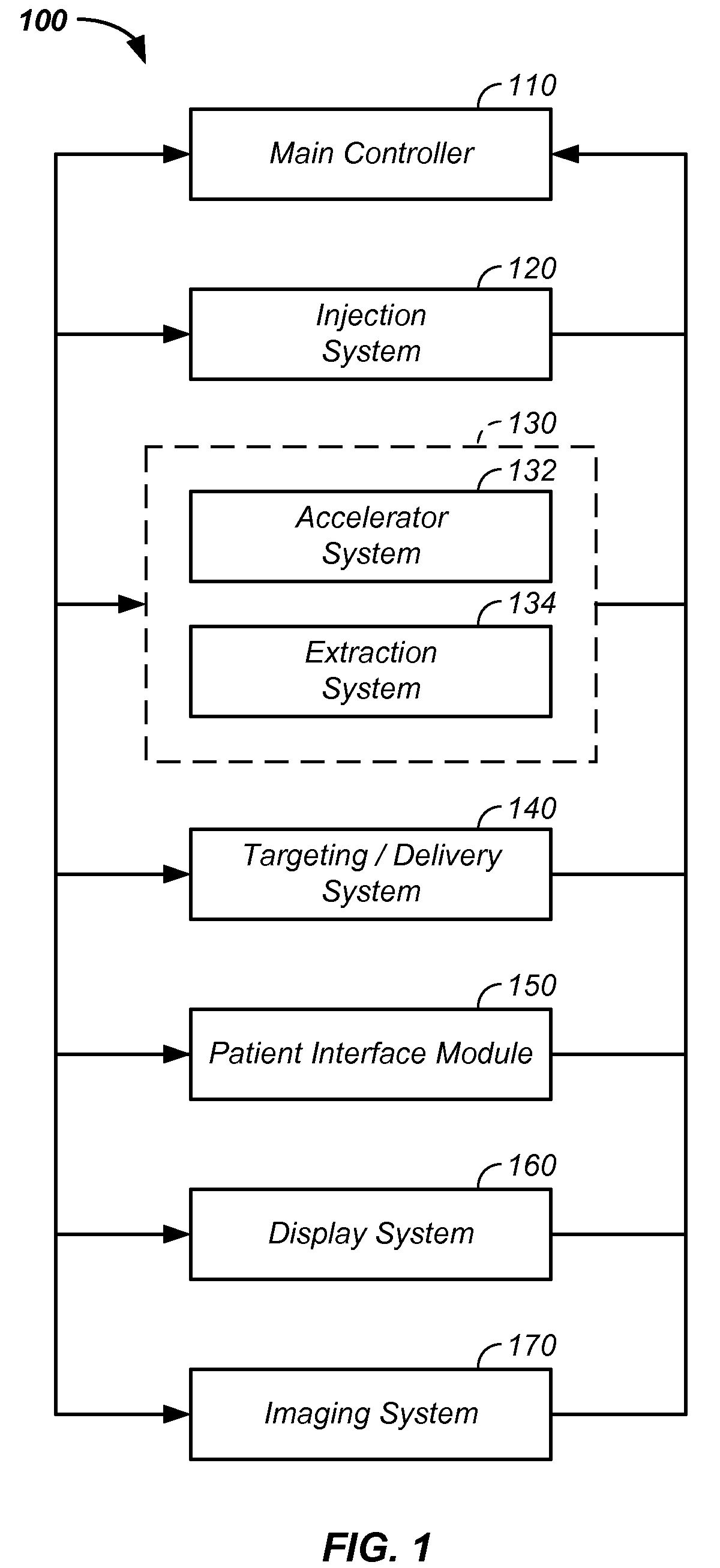
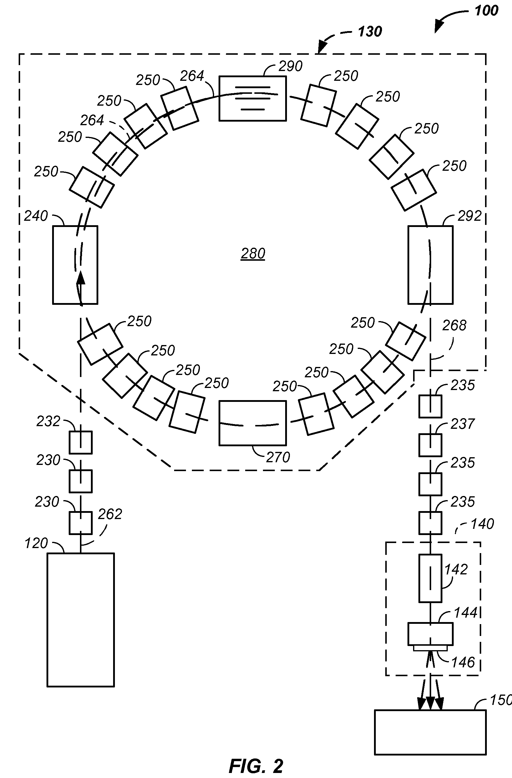
[0148]The invention relates generally to treatment of solid cancers. More particularly, the invention relates to a raster beam method and apparatus for treatment of solid cancers. More particularly, the invention comprises a multi-axis and / or multi-field raster beam charged particle cancer therapy system. The system independently controls patient translation position, patient rotation position, two-dimensional beam trajectory, delivered radiation beam energy, delivered radiation beam intensity, beam velocity, timing of charged particle delivery, and / or distribution of radiation striking healthy tissue. The system operates in conjunction with a negative ion beam source, synchrotron, patient positioning, imaging, and / or targeting method and apparatus to deliver an effective and uniform dose of radiation to a tumor while distributing radiation striking healthy tissue.

[0149]Used in combination with the invention, novel design features of a charged particle beam cancer therapy system are...


PUM


Abstract

The invention relates to a method and apparatus for treatment of solid cancer. More particularly, the invention comprises a multi-axis and / or multi-field raster beam charged particle cancer therapy system. The system independently controls patient translation position, patient rotation position, two-dimensional beam trajectory, delivered beam energy, delivered beam intensity, beam movement velocity, timing of charged particle delivery, and / or distribution of radiation striking healthy tissue. The system operates in conjunction with a negative ion beam source, synchrotron, patient positioning, imaging, and / or targeting method and apparatus to deliver an effective and uniform dose of radiation to a tumor while distributing radiation striking healthy tissue.

Description

CROSS-REFERENCES TO RELATED APPLICATIONS[0001]This application:[0002]is a continuation-in-part of U.S. patent application Ser. No. 12 / 425,683 filed Apr. 17, 2009, which claims the benefit of:[0003]U.S. provisional patent application No. 61 / 055,395 filed May 22, 2008;[0004]U.S. provisional patent application No. 61 / 137,574 filed Aug. 1, 2008;[0005]U.S. provisional patent application No. 61 / 192,245 filed Sep. 17, 2008;[0006]U.S. provisional patent application No. 61 / 055,409 filed May 22, 2008;[0007]U.S. provisional patent application No. 61 / 203,308 filed Dec. 22, 2008;[0008]U.S. provisional patent application No. 61 / 188,407 filed Aug. 11, 2008;[0009]U.S. provisional patent application No. 61 / 188,406 filed Aug. 11, 2008;[0010]U.S. provisional patent application No. 61 / 189,815 filed Aug. 25, 2008;[0011]U.S. provisional patent application No. 61 / 201,731 filed Dec. 15, 2008;[0012]U.S. provisional patent application No. 61 / 205,362 filed Jan. 12, 2009;[0013]U.S. provisional patent applicati...

Claims


Application Information

Patent Timeline
Patent Type & Authority Patents(United States)
IPC IPC(8): A61N5/00
CPCA61N5/10A61N5/1048A61N5/1082H05H7/10H05H13/04A61N2005/1087
Inventor BALAKIN, VLADIMIR
Owner BALAKIN ANDREY VLADIMIROVICH
Why Eureka
Try Eureka