
Digital-to-analog converter

a digital-to-analog converter and converter technology, applied in the field of electronic technologies, can solve the problems of deteriorating the quality of the output signal, generating harmonic waves, increasing the design cost and power consumption of the speed and resolution, etc., and achieves the reduction of in-band noise and out-of-band noise, and increasing power consumption and overall dac area.

Active Publication Date: 2013-12-03
HUAWEI TECH CO LTD
View PDF2 Cites 0 Cited by
  • Summary
  • Abstract
  • Description
  • Claims
  • Application Information

AI Technical Summary

Benefits of technology

The present invention provides a digital-to-analog converter that reduces in-band and out-of-band noise while avoiding the problem of increased power consumption and overall DAC area caused by excessive quantization bits. The solution involves cascading a secondary modulator with less quantization bits behind the primary modulator to reduce non-ideal factors such as static mismatching error and non-ideal switch characteristic. The second processing module processes the quantization noise signal obtained by subtracting the output signal of the secondary modulator from the output signal of the primary modulator to obtain the analog noise signal. The analog noise signal is then added with the first analog signal obtained from processing the output of the secondary modulator to obtain the second analog signal. This reduces in-band and out-of-band noise and results in a lower total harmonic distortion.

Problems solved by technology

The foregoing applications usually demand a high-speed and high-precision DAC, and the improvement of the speed and resolution usually increases design cost and power consumption.
However, an increase of the quantization bits of the quantizer brings non-ideal factors such as a static mismatching error of a current source and a non-ideal characteristic of a switch, and the factors may result in generation of a harmonic wave and deteriorate quality of an output signal.
In addition, the increase of the quantization bits of the quantizer needs to correspondingly increase the number of the dynamic algorithm units and the DAC units, causing an increase to the power consumption and an overall DAC area.

Method used


Image

  • Digital-to-analog converter
  • Digital-to-analog converter
  • Digital-to-analog converter

Examples


Embodiment Construction

[0028]To make the objectives, technical solutions, and advantages of the present invention more comprehensible, the following clearly describes the technical solutions according to the embodiments of the present invention with reference to the accompanying drawings in the embodiments of the present invention. Apparently, the embodiments in the following description are merely a part of rather than all the embodiments of the present invention. All other embodiments obtained by persons skilled in the art based on the embodiments of the present invention without creative efforts shall fall within the protection scope of the present invention.

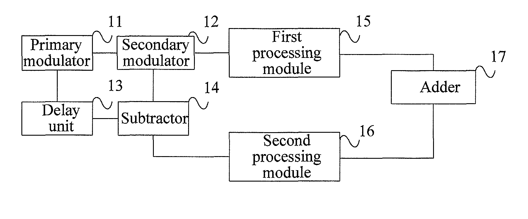
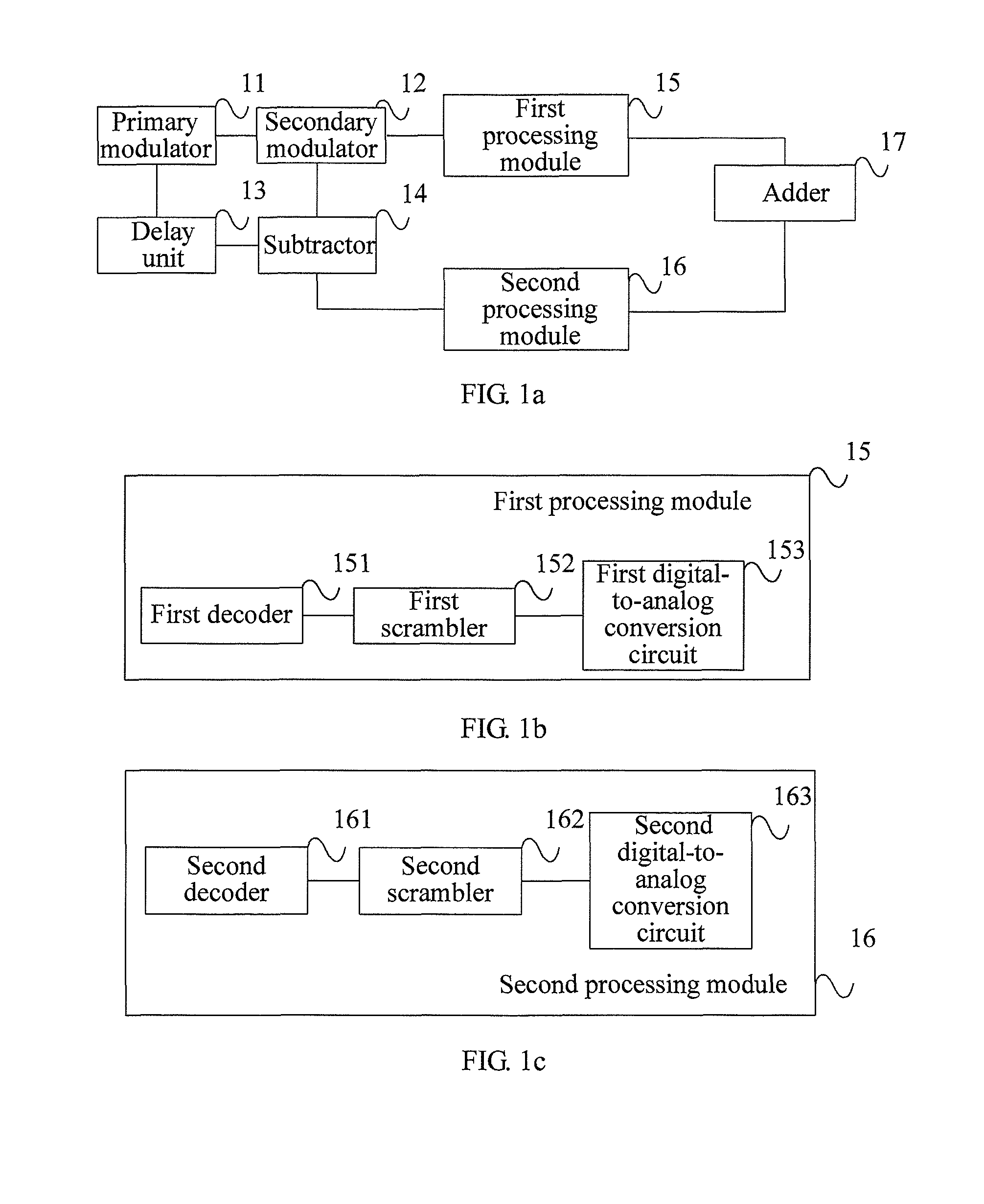
[0029]FIG. 1a is a schematic structural diagram of a digital-to-analog converter according to an embodiment of the present invention. As shown in FIG. 1a, the digital-to-analog converter includes:

[0030]a primary modulator 11, configured to modulate an input M-bit digital signal into an N-bit digital signal, where M and N are positive integers, and ...


PUM


Abstract

An embodiment of the present invention provides a digital-to-analog converter including: a primary modulator; a secondary modulator, connected to the primary modulator; a delay unit, connected to the primary modulator; a subtractor, connected to the delay unit and the secondary modulator separately; a first processing module, configured to perform decoding, dynamic matching, and digital-to-analog conversion in sequence on a B-bit digital signal output by the secondary modulator, so as to obtain a first analog signal; a second processing module, configured to perform decoding, dynamic matching, and digital-to-analog conversion in sequence on an (N−B+1) -bit quantization noise signal output by the subtractor, so as to obtain an analog noise signal; and an adder, connected to the first processing module and the second processing module separately, and configured to add the first analog signal and the analog noise signal, so as to obtain and output a second analog signal.

Description

CROSS-REFERENCE TO RELATED APPLICATION[0001]This application claims priority to Chinese Patent Application No. 201110444075.5, filed on Dec. 27, 2011, which is hereby incorporated by reference in its entirety.FIELD OF THE INVENTION[0002]The present invention relates to the field of electronic technologies, and in particular, to a digital-to-analog converter.BACKGROUND OF THE INVENTION[0003]A digital-to-analog converter (Digital-to-Analog Converter, DAC for short) converts a digital signal into an analog signal which may be sensed by people, and usually converts a digital code into a corresponding voltage signal through weighted summation. The DAC may be applied to, but not limited to, applications of video and image processing and the wireless field. The foregoing applications usually demand a high-speed and high-precision DAC, and the improvement of the speed and resolution usually increases design cost and power consumption. Therefore, it is particularly important to improve the p...

Claims


Application Information

Patent Timeline
Patent Type & Authority Patents(United States)
IPC IPC(8): H03M1/66
CPCH03M1/66H03M7/302H03M3/50H03M3/502
Inventor GUO, SHUBAOCHEN, JUNLEI, GONGLIU, YONGPING
Owner HUAWEI TECH CO LTD
Learn More