Wind turbine blades strain measuring system during static tests

a technology of strain measurement and wind turbine blades, which is applied in the direction of mechanical equipment, machines/engines, instruments, etc., can solve the problems of loss of information, large volume of cabling, and complexity of electro-magnetic interference, and achieve high strain resolution

Inactive Publication Date: 2013-12-10
GAMESA INNOVATION & TECH SA
View PDF6 Cites 2 Cited by
  • Summary
  • Abstract
  • Description
  • Claims
  • Application Information

AI Technical Summary

Benefits of technology

[0008]It is another object of the present invention to provide a wind turbine blades strain measuring system in static tests that facilitates the detection and evaluation of local and global non-linear behaviour such as stress concentrations, buckling or buckling shapes.
[0009]It is another object of the present invention to provide a wind turbine blades strain measuring system in static tests that can be installed fastly and easily.
[0011]In preferred embodiments, the optical fibres are placed whether in a longitudinal direction or in a non-longitudinal direction or in a non-linear shape in given blade sections. Hereby, the system allows obtaining the strain measurements in different locations along the blade for a better adaptation to different requirements.
[0013]In another preferred embodiments the optical fibres are bonded to the outer skin of the blade, into grooves in the outer skin of the blade or embedded between two structural laminates of the blade. Hereby, the system allows obtaining the strain measurements in different locations in the transversal section of the blade for a better adaptation to different requirements.

Problems solved by technology

With two to four electrical wires per gauge, cabling volume, complexity and vulnerability to electro-magnetic interference become significant and disturbing.
Additionally, the discrete nature of this kind of measurements implies loss of information in case of non-linear behaviour in the area between two strain gauges.

Method used


Image

  • Wind turbine blades strain measuring system during static tests
  • Wind turbine blades strain measuring system during static tests
  • Wind turbine blades strain measuring system during static tests

Examples


Embodiment Construction

[0020]A typical wind turbine blade may have a length between 20 and 60 meters or more and it is constructed with composite materials such as glass-reinforced plastics (GRP). There are so many factors that can damage a wind turbine blade such as fatigue, wind gusts, lightning strikes, aerodynamic interaction between wind turbines, some of them causing unpredictable loads on the blade, that it is very important to have good blade strain measurement systems to be used in static tests not only for certification purposes but also to provide valuable information regarding the behavior of a blade subjected to predetermined loads, particularly the deflections and strains of a cantilevered blade.

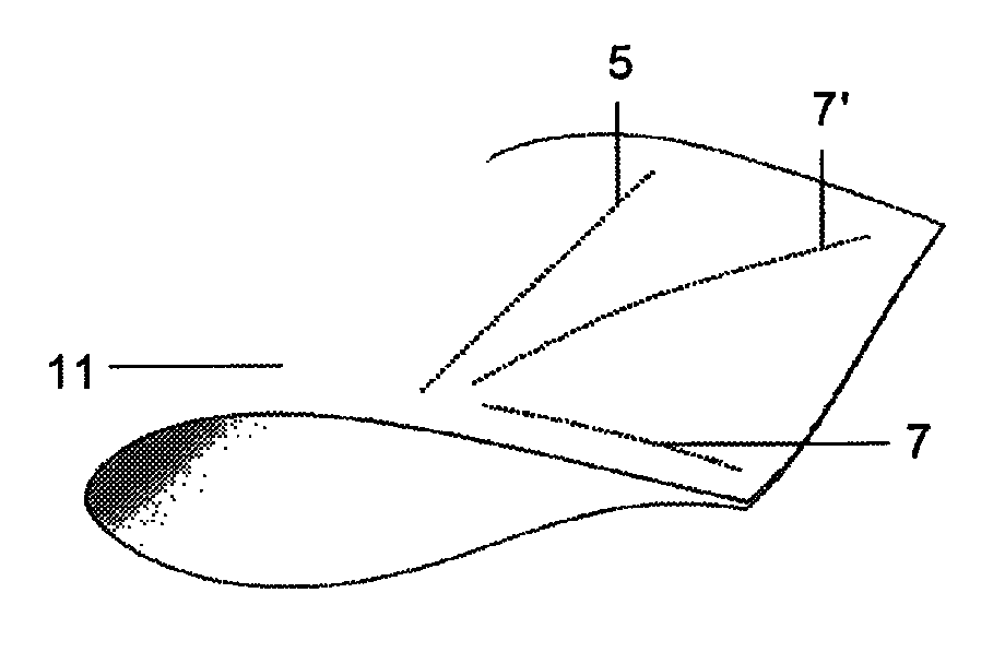
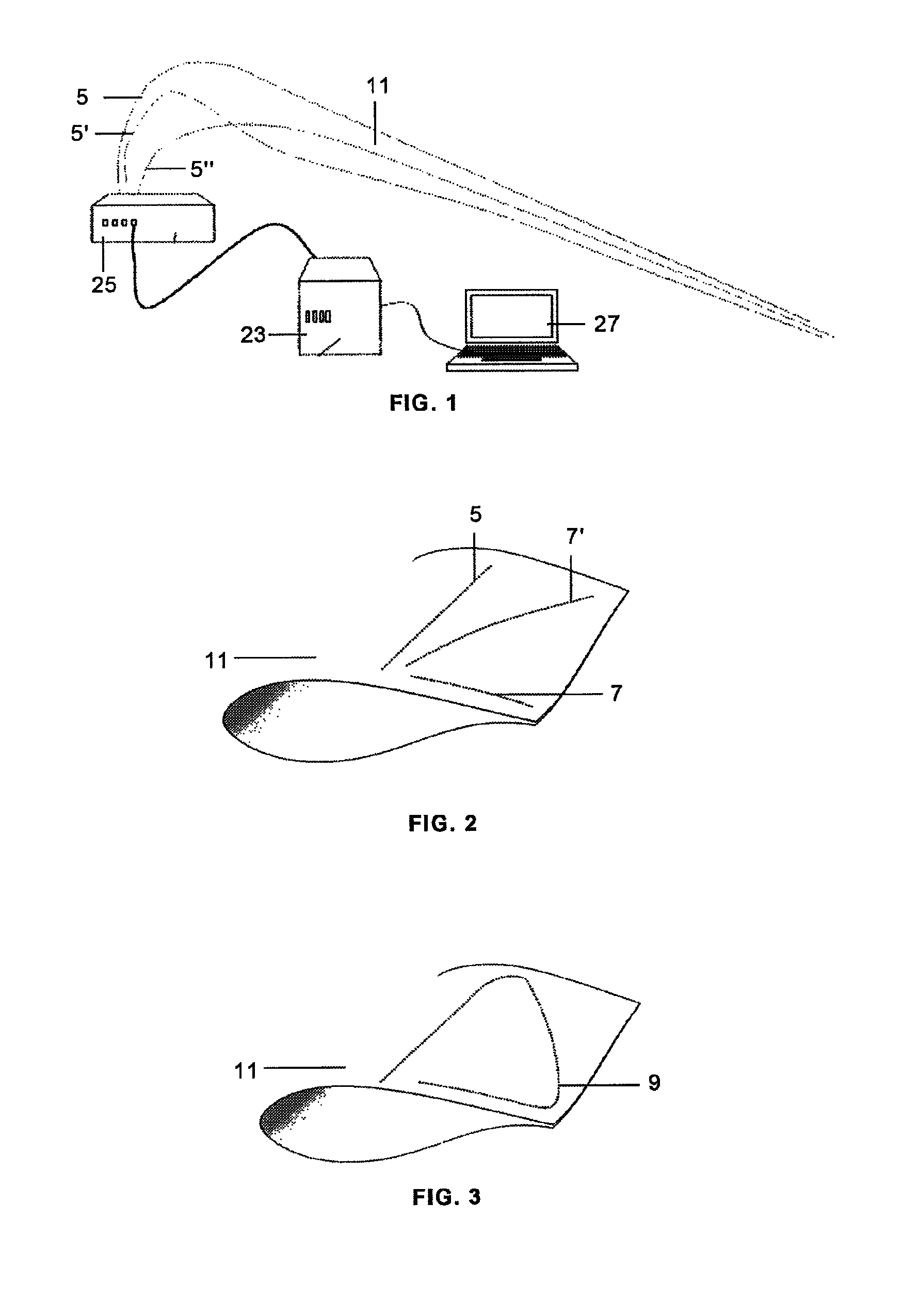
[0021]Following FIG. 1 it can be seen that a wind turbine blades strain measurement system in static tests according to the present invention comprises:

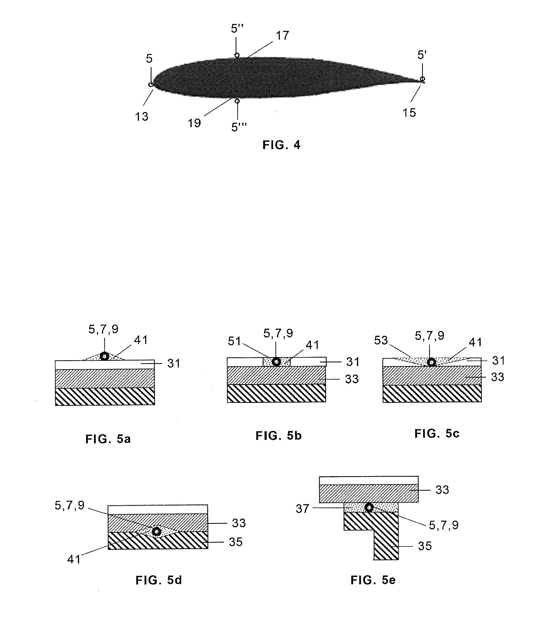
[0022]a) A plurality of mono-mode optical fibres 5, 5′, 5″′ attached to the blade 11 which is subjected to said tests.

[0023]b) An equipment for measu...


PUM


Abstract

A current transformer (5) having a plurality of primary and secondary windings, comprising a top Strain measuring system of wind turbine blades (11) during the performance of static tests that comprises an equipment for measuring the strain at multiple locations in mono-mode optical fibers (5, 7, 9) using Rayleigh scattered light, that includes an OBR interrogator (23), an interface device (25) and an Acquisition System (27), said mono-mode optical fibers (5, 7, 9) being attached to the blade (11) subjected to said tests for obtaining high spatial resolution measurements of the blade strain during said tests. Said optical fibers (5, 7, 9) may be placed whether in a longitudinal direction or in a non-longitudinal direction or in a non-linear shape in given blade sections and may be bonded whether to the outer skin (31) of the blade (11), or into grooves (51, 53) in the outer skin (31) of the blade (11) or embedded between two structural laminates (33, 35) of the blade (11).

Description

FIELD OF THE INVENTION[0001]This invention relates to the static tests performed to wind turbine blades for certification and other purposes and in particular to the systems used for measuring strain in said tests.BACKGROUND[0002]Current wind turbine blade certification requires performing several static tests on the blade to confirm the blade capability to withstand the expected loads, particularly static strength tests to check the blade behaviour under extreme design loads, fatigue tests to check the blade's ability to withstand the operating loads for its design life and other tests in order to characterize physical properties of the blade such as weight, centre of gravity or natural modes and frequencies.[0003]These tests are usually carried out in a test bench in which the blade is bolted to a rigid structure and then static or dynamic loads are applied to the blade by means of different methods.[0004]Current test systems rely on a set of strain gauges to determine the strain ...

Claims


Application Information

Patent Timeline
Patent Type & Authority Patents(United States)
IPC IPC(8): G01B11/16
CPCF03D1/06G01B11/18G01M5/0016G01M5/0041G01M5/0091F05B2260/83Y02E10/721Y02E10/72
Inventor CRIADO ABAD, ALFREDORIEZU CORPAS, MIGUELFERNANDEZ LOPEZ, ANTONIOGUEMES GORDO, ALFREDO
Owner GAMESA INNOVATION & TECH SA
Why Eureka
Try Eureka