
Fluence monitoring devices with scintillating fibers for X-ray radiotherapy treatment and methods for calibration and validation of same

a fluence monitoring and scintillating fiber technology, applied in the field can solve the problems of affecting the actual dose delivered, affecting the accuracy of x-ray radiation treatment, and being subject to delivery and leaf positioning errors, so as to minimize the attenuation of the radiation beam

Active Publication Date: 2013-12-17
UNIV LAVAL
View PDF11 Cites 8 Cited by
  • Summary
  • Abstract
  • Description
  • Claims
  • Application Information

AI Technical Summary

Benefits of technology

The patent text describes a new design for a scintillating fiber and phantom slab assembly that are thin enough to minimize the loss of radiation energy. This allows for better detection and analysis of the incoming radiation beam.

Problems solved by technology

These advanced modalities of treatment (such as intensity modulated radiation therapy (IMRT), intensity modulated arc therapy (IMAT), or stereotactic body radiotherapy (SBRT)) are inherently more complex in planning, delivery and software / hardware communication than their static counterparts, and are often subject to delivery and leaf positioning errors.
As these advanced treatment modalities use complex combinations of often small and irregular field shapes to produce conformal radiation dose distributions at a treatment region (e.g. a tumor site), a leaf positioning error of only a few millimeters can have dire repercussions on the actual dose delivered, greatly impacting the quality of the treatment.
Large deviations from the planned treatment can lead to significant under-dosage or over-dosage, and may result in severe injury to a patient or even death.
Typical, off-line quality assurance protocols are currently inadequate to assess the quality of such treatment procedures.

Method used


Image

  • Fluence monitoring devices with scintillating fibers for X-ray radiotherapy treatment and methods for calibration and validation of same
  • Fluence monitoring devices with scintillating fibers for X-ray radiotherapy treatment and methods for calibration and validation of same
  • Fluence monitoring devices with scintillating fibers for X-ray radiotherapy treatment and methods for calibration and validation of same

Examples


Embodiment Construction

[0040]It will be appreciated that numerous specific details are set forth in order to provide a thorough understanding of the exemplary embodiments described herein. However, it will be understood by those of ordinary skill in the art that the embodiments described herein may be practiced without these specific details. In other instances, well-known methods, procedures and components have not been described in detail so as not to obscure the embodiments described herein. Furthermore, this description is not to be considered as limiting the scope of the embodiments described herein in any way, but rather as merely describing the implementation of various embodiments as described herein.

[0041]While certain features have been illustrated and described herein, many modifications, substitutions, changes, and equivalents will now occur to those of ordinary skill in the art. It is, therefore, to be understood that the appended claims are intended to cover such modifications and changes as...


PUM


Abstract

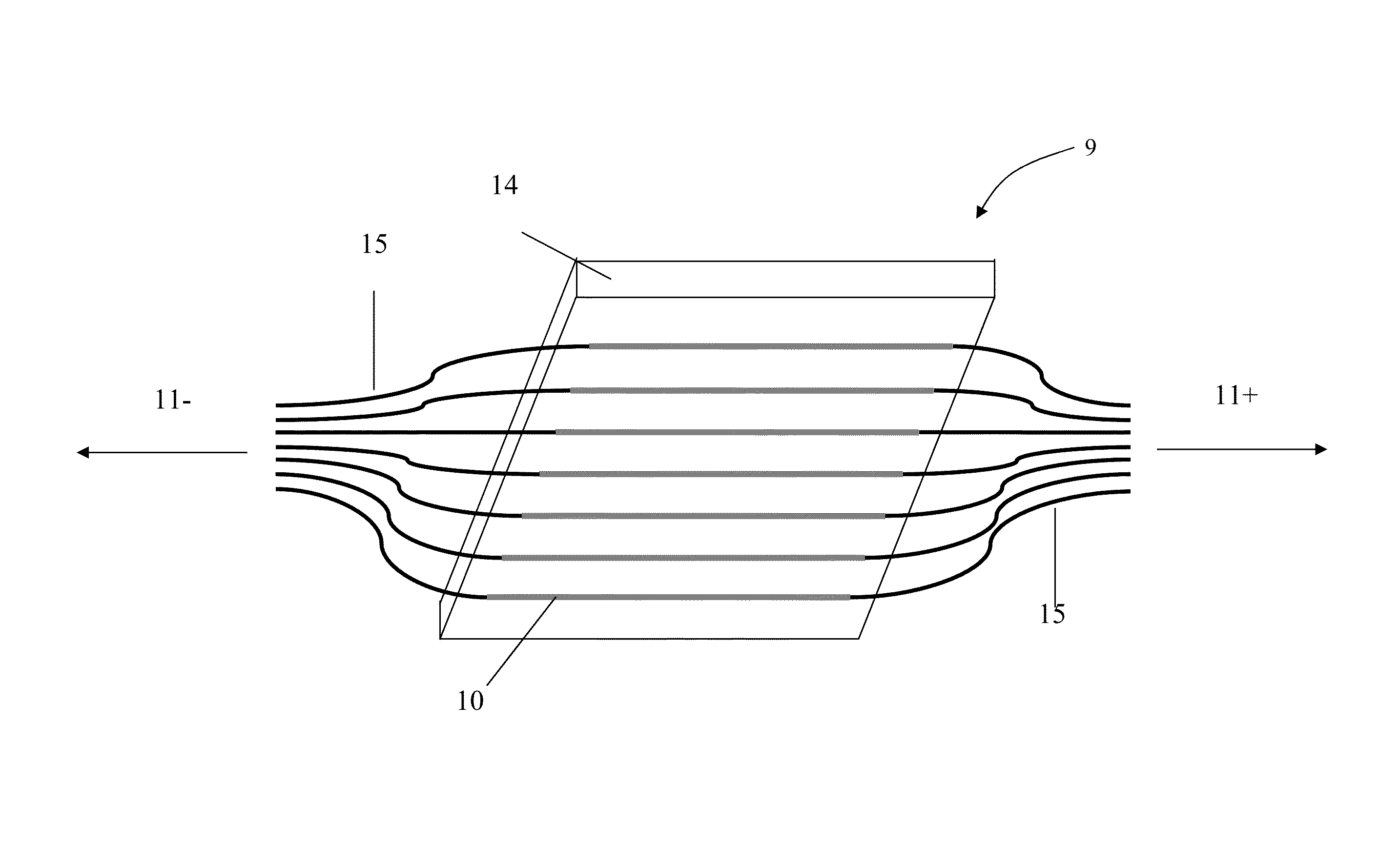
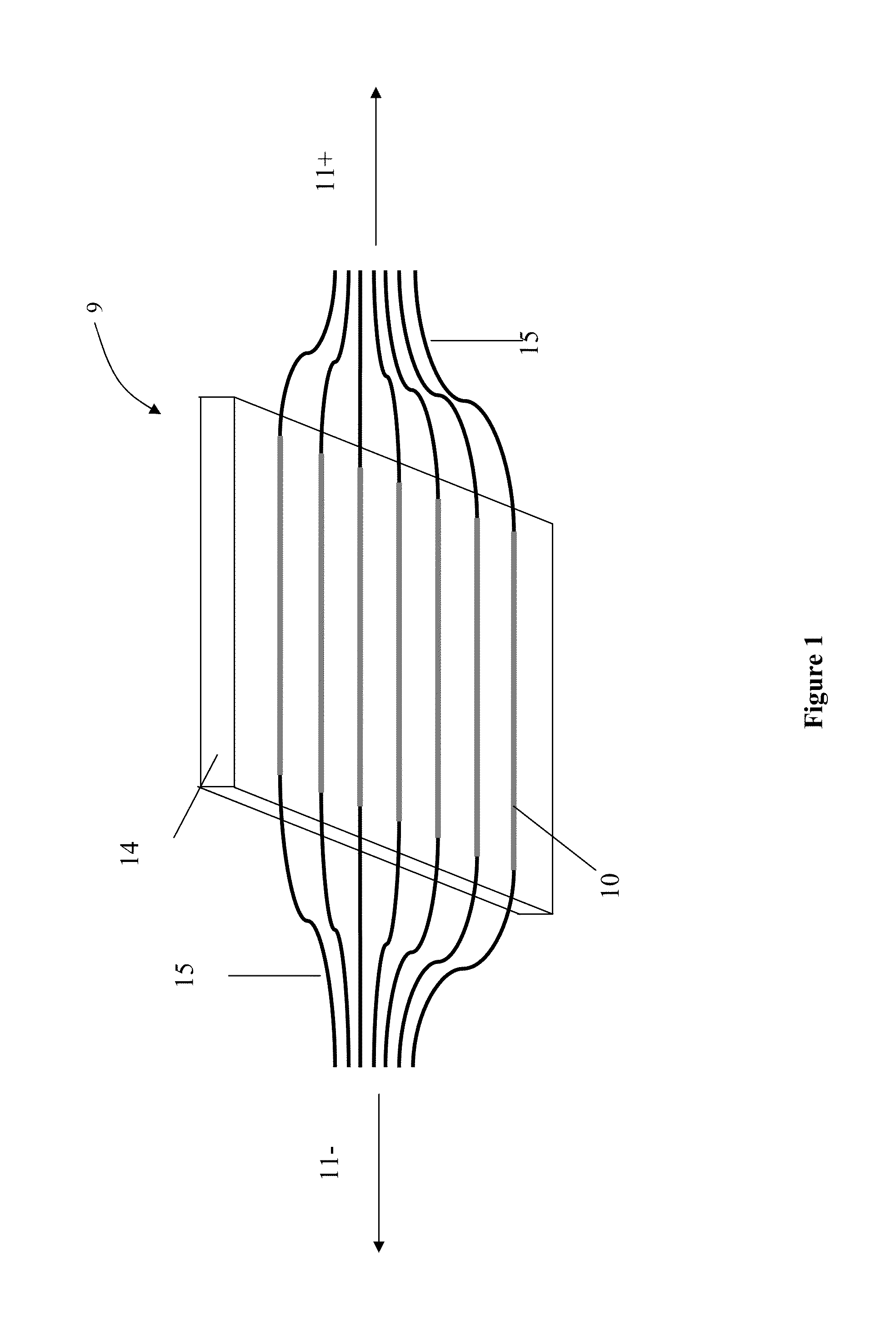
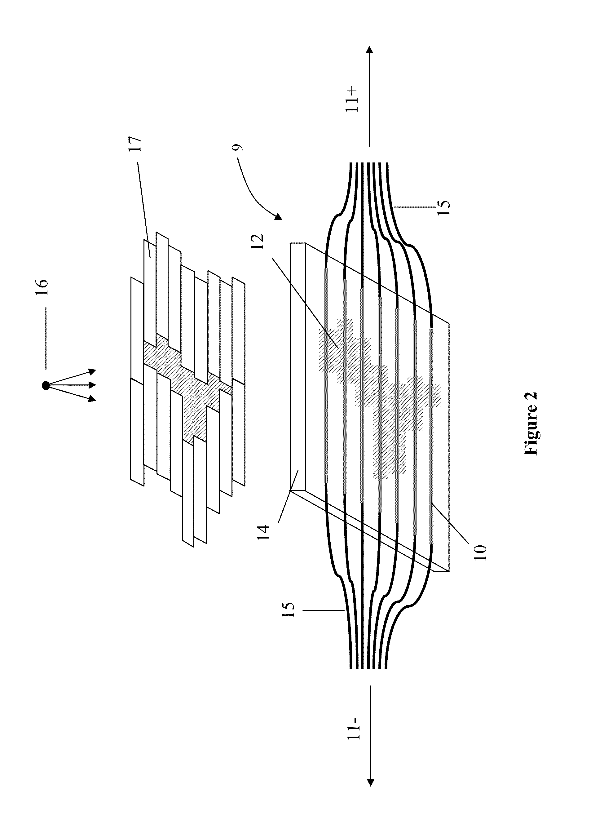
According to one aspect, a fluence monitoring detector for use with a multileaf collimator on a radiotherapy machine having an x-ray radiation source. The fluence monitoring detector includes a plurality of scintillating optical fibers, each scintillating optical fiber configured to generate a light output at each end thereof in response to incident radiation pattern thereon from the radiation source and multileaf collimator, a plurality of collection optical fibers coupled to the opposing ends of the scintillating optical fibers and operable to collect the light output coming from both ends of each scintillating optical fiber, and a photo-detector coupled to the collection optical fibers and operable to converts optical energy transmitted by the collection optical fibers to electric signals for determining actual radiation pattern information.

Description

RELATED APPLICATIONS[0001]This application claims the benefit of U.S. Provisional patent application Ser. No. 61 / 375,125 filed Aug. 19, 2010 and entitled FLUENCE MONITORING DEVICES WITH SCINTILLATING FIBERS FOR X-RAY RADIOTHERAPY TREATMENT AND METHODS FOR CALIBRATION AND VALIDATION OF SAME, the entire contents of which are hereby incorporated by reference herein for all purposes.FIELD[0002]The embodiments described herein relate to the field of x-ray radiation treatment, and in particular to fluence monitoring devices with scintillating fibers, and validation methods for verification of the delivery and conformity of x-ray radiation dose patterns using such fluence monitoring devices.INTRODUCTION[0003]Radiation therapy, or “radiotherapy”, is the medical use of ionizing radiation to control malignant cells in cancer treatments. Most frequently, radiation therapy makes use of x-ray beams originating from outside the patient body (i.e. external x-ray radiotherapy). Many of the most adv...

Claims


Application Information

Patent Timeline
Patent Type & Authority Patents(United States)
IPC IPC(8): G01D18/00G01T1/20
CPCG01T1/201A61N5/1075A61N2005/1076
Inventor BEAULIEU, LUCGINGRAS, LUCGOULET, MATHIEU
Owner UNIV LAVAL
Learn More