Biplane X-ray imaging system

a x-ray imaging and plane technology, applied in the field of plane x-ray imaging system, can solve the problems of insufficient mobility of c-arm x-ray machines using fluoroscopy imaging, inadequate for all applications, etc., and achieve the effect of good, quick and simple adjustmen

Inactive Publication Date: 2013-12-17
SIEMENS HEALTHCARE GMBH
View PDF17 Cites 11 Cited by
  • Summary
  • Abstract
  • Description
  • Claims
  • Application Information

AI Technical Summary

Benefits of technology

[0005]It is the object of the present invention to provide an X-ray imaging system which not only enables good image quality in respect of spatial resolution but also allows good visualization of soft tissue.
[0007]The biplane X-ray imaging system according to the invention has two recording units arranged in different planes, each such unit having an X-ray detector and an X-ray source, wherein the first recording unit is formed by a phase-contrast recording unit for phase-contrast X-ray imaging. Phase-contrast X-ray imaging exploits the fact that different types of body tissue diffract X-ray beams to different degrees. The phase shift effect when an X-ray beams passes through an examination subject is significantly stronger than the absorption effect of the material penetrated by the X-ray radiation. By means of phase-contrast X-ray imaging soft parts can be represented with particularly high contrast in X-ray examinations. In combination with a second, conventional recording unit (which measures the X-ray radiation attenuated through absorption in an examination subject) the biplane X-ray imaging system according to the invention can provide not only conventional projection images but also particularly high-quality visualizations of soft parts. This makes such a system also suitable for minimally invasive interventions and minimally surgical interventional procedures.
[0008]According to an embodiment of the invention the first recording unit embodied for phase-contrast X-ray imaging has an X-ray tube assembly, an X-ray detector, a phase grating which is disposed between an examination subject and the X-ray detector, and an amplitude grating which is disposed between the phase grating and the X-ray detector. In order to generate quasi-coherent X-ray radiation, as is required for phase-contrast X-ray imaging, two alternatives can be used: According to a first alternative the first recording unit has a further grating which is disposed behind the X-ray tube assembly of the first recording unit and is embodied for the purpose of generating coherent X-ray radiation from the non-coherent X-ray radiation of the X-ray tube assembly. According to a second alternative the X-ray tube assembly of the first recording unit has a plurality of field-emission X-ray sources for emitting quasi-coherent X-ray radiation. Integrating an X-ray tube assembly having field-emission X-ray sources into a phase-contrast X-ray imaging system eliminates the need for the complex source grating for generating monochromatic X-ray radiation, because the field-emission X-ray sources constitute a simple and effortless means of generating mutually coherent X-ray beams with a narrow focus. This enables the X-ray imaging system to be manufactured in a particularly compact design and particularly economically.
[0012]In the case of a field-emission X-ray source or, as the case may be, the corresponding field-emission cathode, electrons are emitted as a result of a sufficiently high electric field being applied. Field emission is achieved e.g. by means of a simple diode mode in which a bias voltage is applied between anode and cathode. Electrons are emitted by the cathode when the electric field exceeds the emission threshold. A triode construction can also be provided in which a gate electrode is disposed close to the cathode. Electrons are emitted here by applying a bias voltage between gate and cathode. The emitted electrons are then accelerated by means of a high voltage between gate and anode. Field-emission cathodes a very high, readily controllable and easily focusable electron beam current. All in all, by means of the field-emission X-ray sources the invention affords the advantages of low heat generation by the field-emission X-ray tube assembly and a low weight, not only on account of the field-emission tube assembly itself but also as a result of the omission or reduction in size of a cooling system. Furthermore such a field-emission tube assembly is highly compact in comparison with conventional X-ray tube assemblies, thereby establishing the precondition for providing a high-quality, laminar X-ray source having a surface area of many focal points arranged adjacent to one another. This is ensured in particular by means of an array having a plurality of field-emission tube assemblies. The useful life of field-emission tube assemblies is also significantly higher than that of known X-ray tube assemblies using thermal cathodes. In addition, by comparison with a thermal cathode a field-emission cathode can be started quickly without heating. Moreover, a higher spatial resolution can be achieved for X-ray images thanks to the readily focusable electron current.
[0018]Both recording units beneficially have C-arms. The recording units are advantageously disposed on at least one robotic arm, in particular a 6-axis articulated-arm robot, in order to provide particularly good, quick and simple adjustability in three dimensions.

Problems solved by technology

For this reason known mobile C-arm X-ray machines using fluoroscopy imaging are not sufficient, since generally these only deliver 2D images with low soft-part resolution or their X-ray power is too low to achieve sufficiently good image quality for more complex interventions.
100 μm, a flat-panel detector based on solid-state material (e.g. amorphous silicon) possesses good spatial resolution, though in connection with conventional X-ray imaging this is not adequate for all applications, such as the visualization of tumor tissue for example.

Method used


Image

  • Biplane X-ray imaging system
  • Biplane X-ray imaging system
  • Biplane X-ray imaging system

Examples


Embodiment Construction

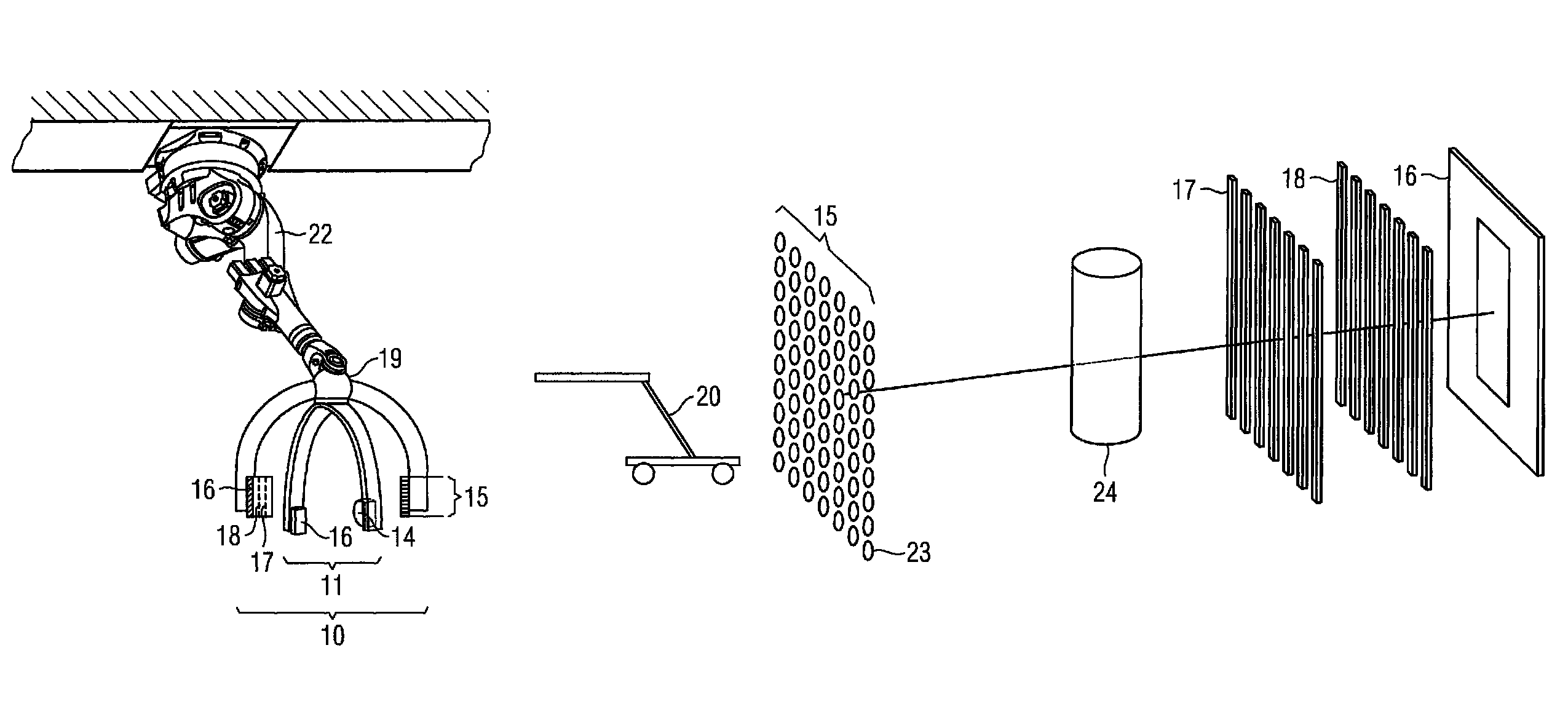
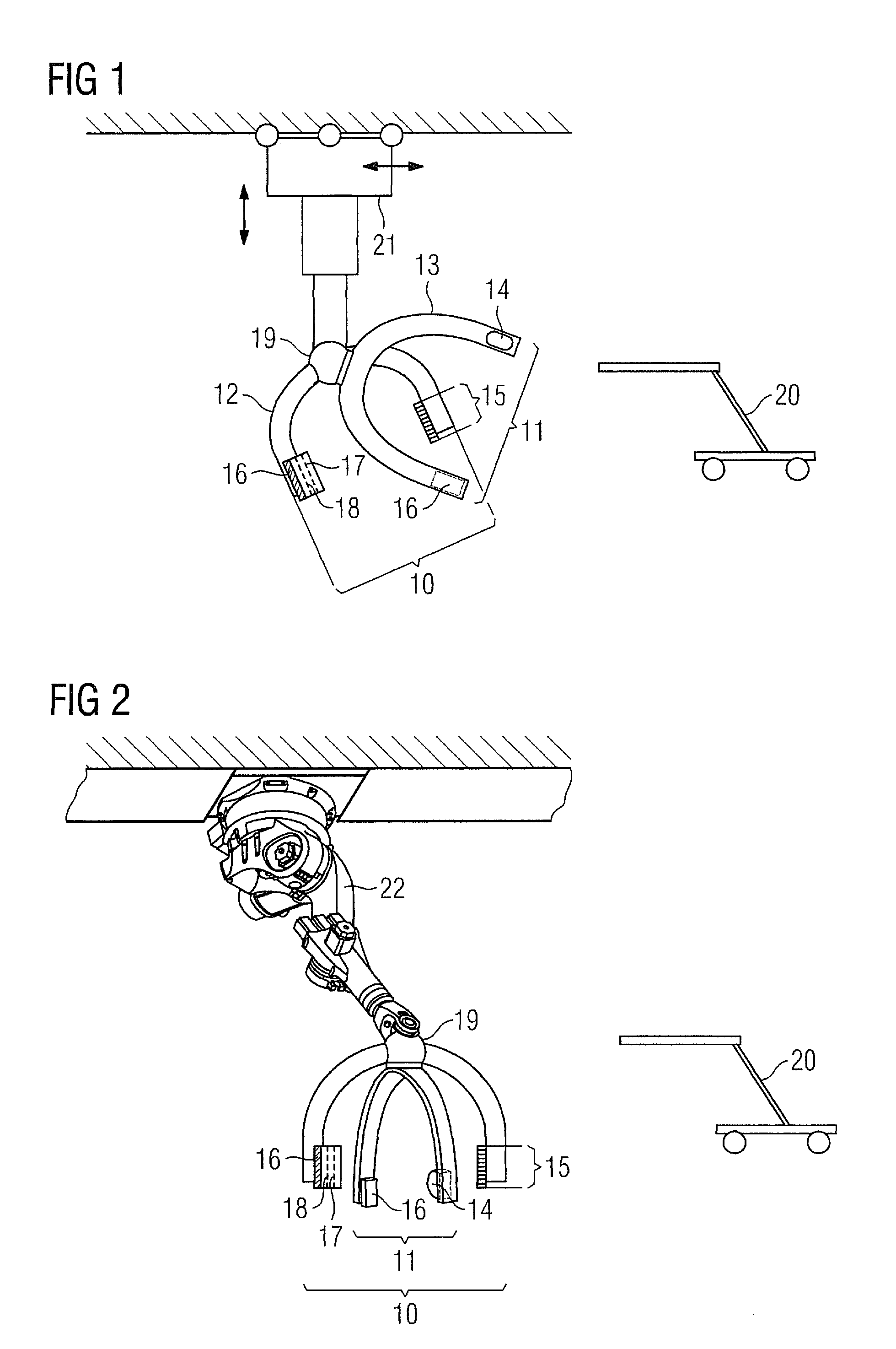
[0028]FIG. 1 and FIG. 2 each show an inventive biplane X-ray imaging system having two recording units disposed in different planes, a first recording unit 10 embodied for phase-contrast X-ray imaging and a second, “conventional” recording unit 11 embodied for fluoroscopy imaging. The two recording planes are offset with respect to each other by e.g. 90°.

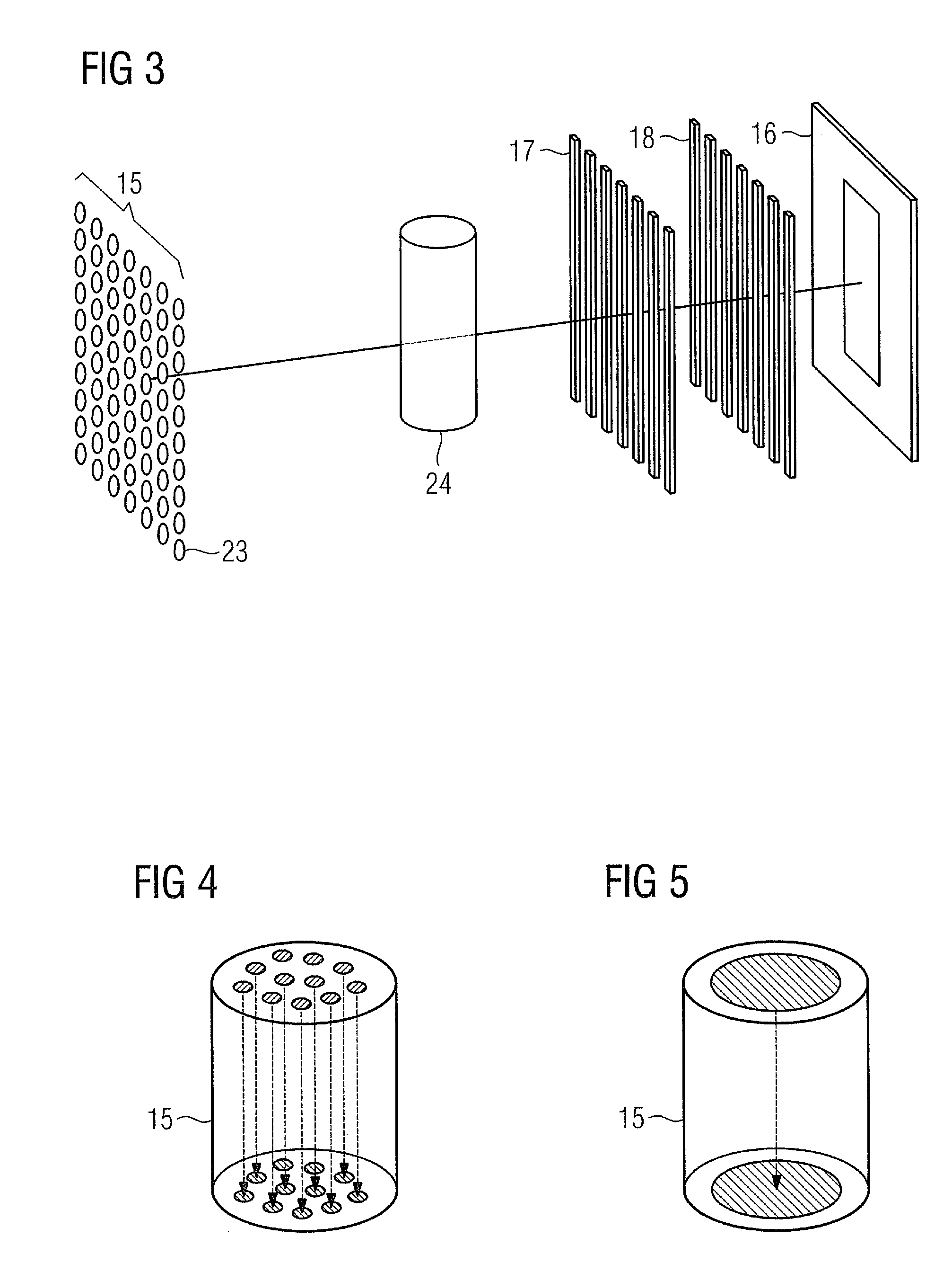
[0029]The second, “conventional” recording unit 11 in the form of a second C-arm 13 has a conventional X-ray tube assembly 14 and an X-ray detector 16 which can be for example a solid-state-based flat-panel detector. Instead of the conventional X-ray tube assembly 14, a field-emission tube assembly 15 having a single field-emission cathode—as shown in FIG. 5—or a field-emission tube assembly 15 having a plurality of field-emission cathodes—as shown in FIG. 4—can also be used. It is also possible to use a plurality of field-emission tube assemblies 15, each having one field-emission cathode. In the case of the second recording unit 1...


PUM

PropertyMeasurementUnit
biplane X-ray imagingaaaaaaaaaa
fluoroscopy imagingaaaaaaaaaa
3D imagingaaaaaaaaaa

Abstract

A biplane X-ray imaging system is provided. The biplane X-ray imaging system has two recording units disposed in different planes. Each of the recording units has an X-ray detector and an X-ray source. The first recording unit is a phase-contrast recording unit for phase-contrast X-ray imaging. The second recording unit is a conventional recording unit for conventional x-ray imaging.

Description

CROSS REFERENCE TO RELATED APPLICATIONS[0001]This application claims priority of German application No. 10 2010 019 990.7 filed May 10, 2010, which is incorporated by reference herein in its entirety.FIELD OF THE INVENTION[0002]The invention relates to a biplane X-ray imaging system.BACKGROUND OF THE INVENTION[0003]Minimally invasive interventions and minimally surgical interventional procedures on patients are increasingly replacing traditional surgical operations. A factor of crucial importance in this regard is good anatomical and functional medical imaging, in particular of soft tissue, in the case of interventions involving the heart and liver for example. For this reason known mobile C-arm X-ray machines using fluoroscopy imaging are not sufficient, since generally these only deliver 2D images with low soft-part resolution or their X-ray power is too low to achieve sufficiently good image quality for more complex interventions. Good 3D imaging is provided e.g. by a permanently...

Claims


Application Information

Patent Timeline
Patent Type & Authority Patents(United States)
IPC IPC(8): G01N23/04
CPCA61B6/4014A61B6/4064A61B6/4417A61B6/4441A61B6/4464A61B6/484A61B6/487G01N23/046G03B42/02G03B42/026A61B6/4458A61B6/4035G01N2223/612G21K2207/005A61B6/4021A61B6/4291G01N2223/419
Inventor MASCHKE, MICHAEL
Owner SIEMENS HEALTHCARE GMBH
Why Eureka
Try Eureka