Array stimulator

a stimulator and array technology, applied in the field of electric devices, can solve the problems of limited stimulation intensity, localized pain relief, and a tendency to produce a rather short-lived effect, and achieve the effects of reducing space requirements, reducing noise, and reducing nois

a stimulator and array technology, applied in the field of electric devices, can solve the problems of limited stimulation intensity, localized pain relief, and a tendency to produce a rather short-lived effect, and achieve the effects of reducing space requirements, reducing noise, and reducing nois

US8612018B2Active Publication Date: 2013-12-17GILLBE IVOR STEPHEN

Image

  • Array stimulator
  • Array stimulator
  • Array stimulator

Examples


Embodiment Construction

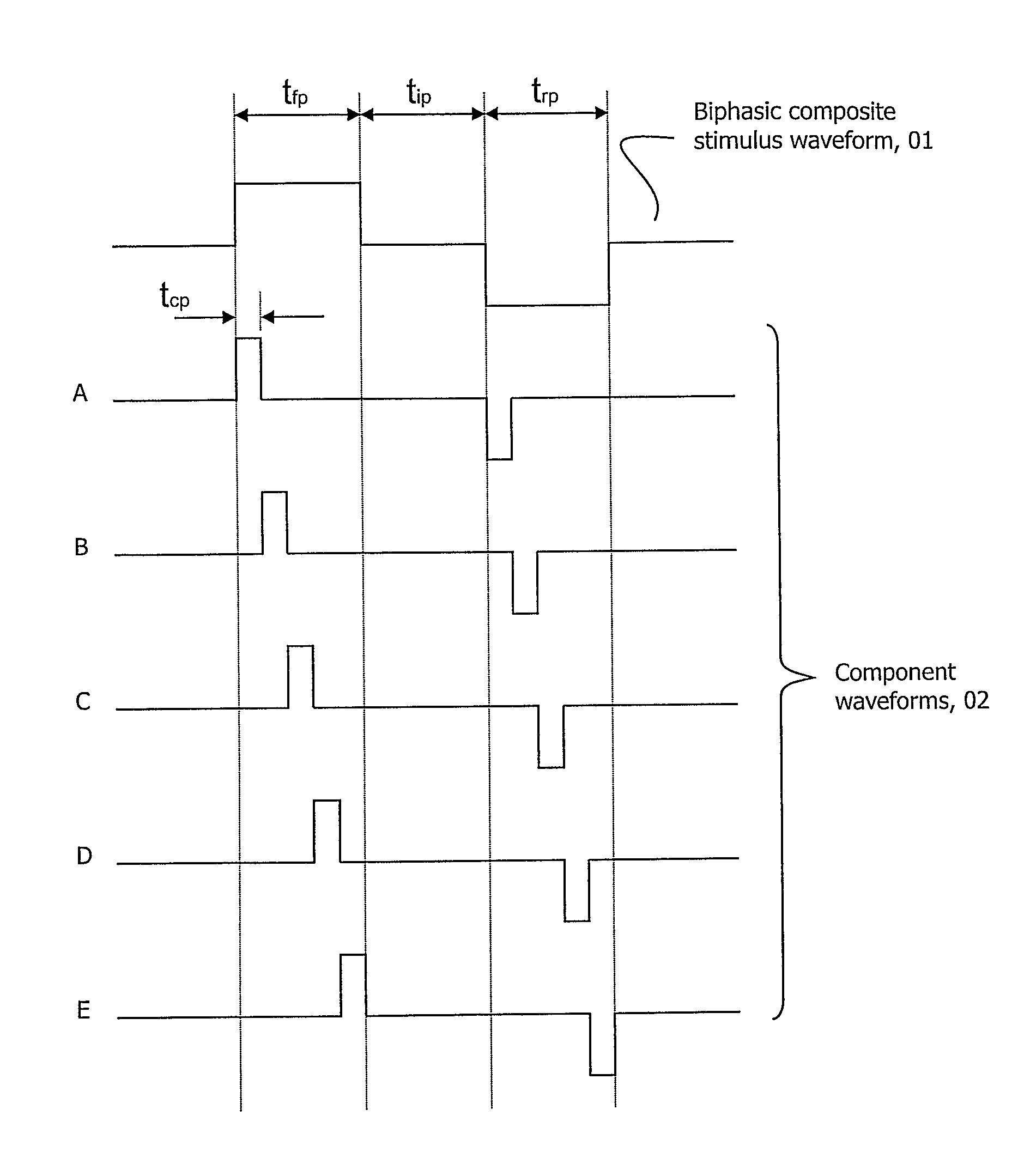
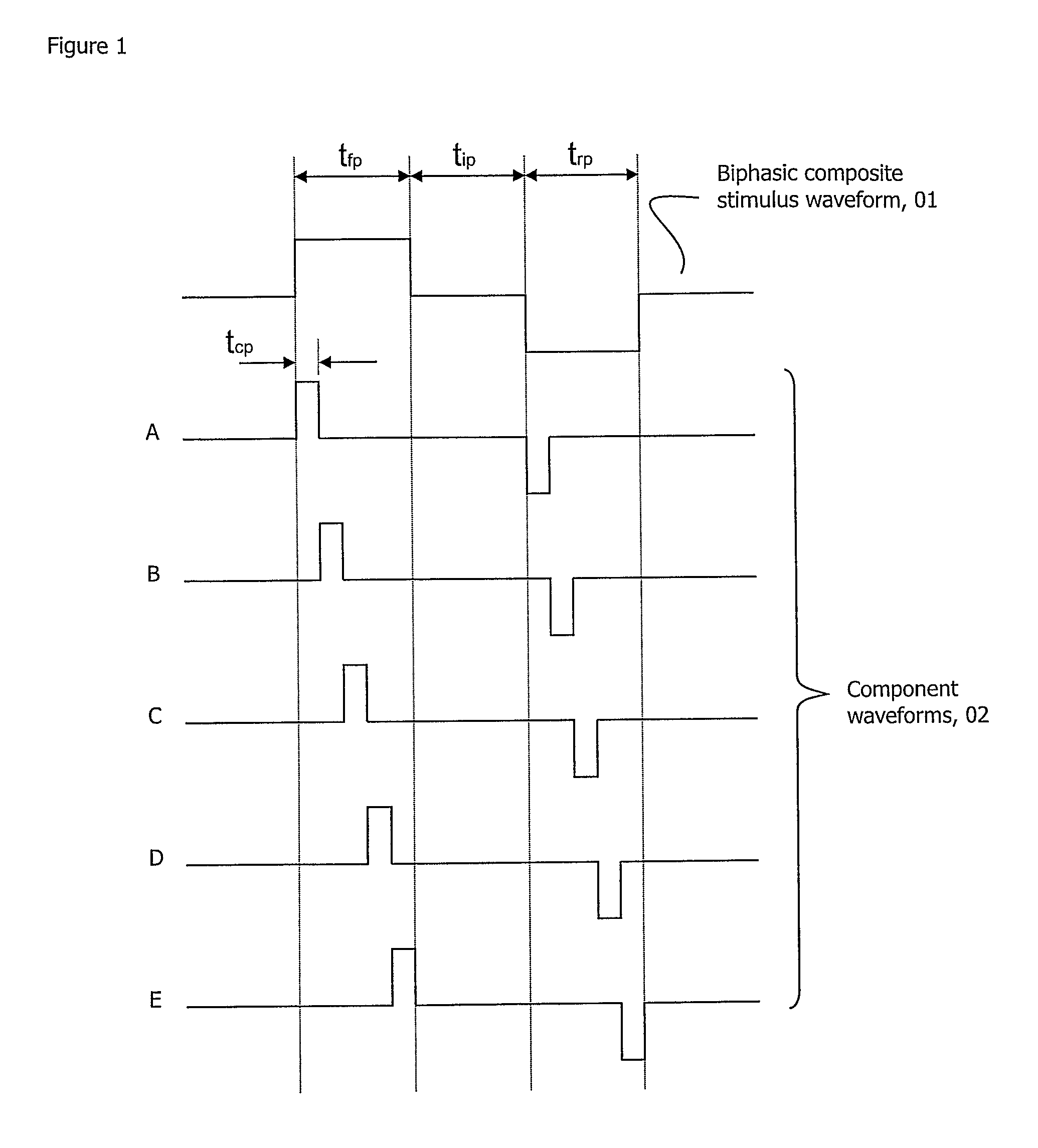
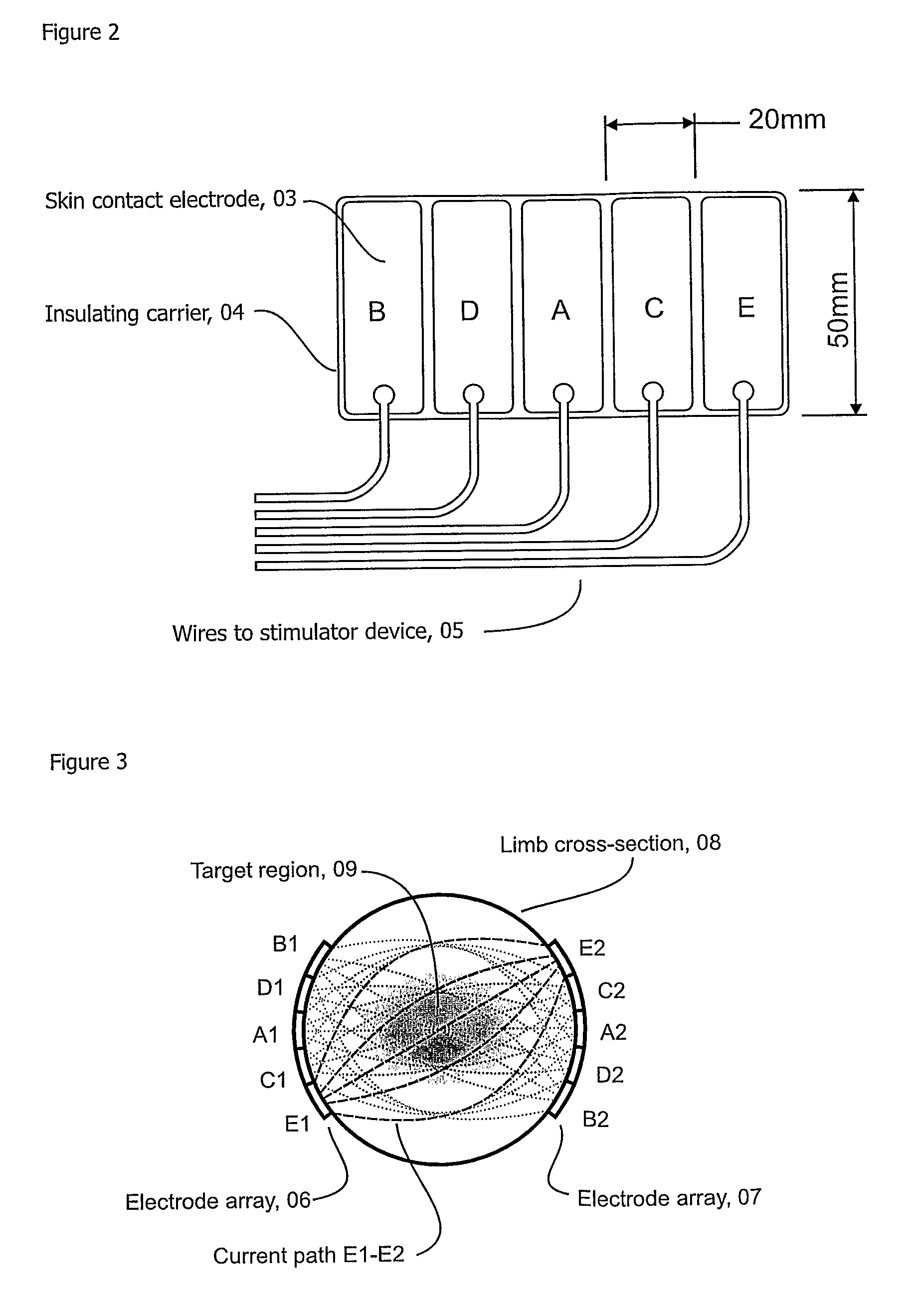
[0114]The invention can be illustrated by considering examples of its application to transcutaneous and implanted stimulators. The figures illustrating electrode arrays may be considered to be representative either of a clinical situation or of a corresponding mathematical model of the tissues used to derive the appropriate component waveforms. The pulses in the figures can be considered to be representative of current, voltage, charge or energy, depending on the method of control used by the stimulator device.

[0115]Referring to FIG. 1, waveform 01 is a composite waveform required to affect the behaviour of excitable tissue in, for example, a transcutaneous nerve stimulation application. The waveform in this example consists of balanced forward and reverse composite pulses, the forward pulse of duration tfp (which may typically be 50, 100, 500 or 1000 μs) and the reverse pulse of duration trp, with tfp=trp, so that the net current flowing in the tissues is zero. Net zero current flo...


PUM


Abstract

An array stimulator has a plurality of electrodes in an array, the electrodes forming a plurality of electrode pairs, and a signal generator for generating signals to the electrodes so as to generate electrical pulse in a patient to which the stimulator has been applied either transcutaneously or by implantation. Those electrical pulses form a composite pulse in the patient which stimulates the nervous system of the patient. The composite pulse has a duration between 4 μs and 1500 μs and a maximum voltage between 2V and 50V when the stimulator is implanted, and 15V to 500V when applied transcutaneously. The electrical pulses themselves are significantly shorter duration than the composite pulse, so they stimulate the nervous system of the patient much less than the composite pulse or not at all.

Description

CROSS-REFERENCE TO RELATED APPLICATIONS[0001]This application claims priority on International Application No. PCT / GB2008 / 001723, filed May 20, 2008 and GB0709834.6 filed May 22, 2007, both of which are incorporated herein by reference in its entirety.FIELD OF THE INVENTION[0002]The present invention relates to an electrical device designed to produce currents that affect the behaviour of nerves and other excitable tissues lying at various distances from the electrodes and provides apparatus and methods for application of such device.BACKGROUND OF THE INVENTION[0003]Electrical stimulation of nerves has been in use for therapeutic purposes for more than 40 years.[0004]For example Melzack and Wall 1965 described how analgesia could be produced when Aβ nerve fibres are stimulated at 100 Hz, a frequency that none of the other afferent fibres can follow faithfully. Wall 1986 produced these effects by applying the current through needles inserted into the patient's nerves. To avoid possib...

Claims


Application Information

Patent Timeline
17 Dec 2013
Publication
US8612018B2
IPC
A61N1/36
CPC
A61N1/0551; A61N1/36021; A61N1/36071; A61N1/0553; A61N1/36017
Inventors
GILLBE, IVOR STEPHEN