
System and method for distributed simulation in which different simulation servers simulate different regions of a simulation space

a simulation server and simulation space technology, applied in the field of simulation systems, can solve the problems of large computational workload, large computation volume, and inability to meet the needs of many computer systems, and achieve the effect of reducing the amount of data transmitted and high resolution images

Active Publication Date: 2013-12-17
LINDEN RES
View PDF78 Cites 17 Cited by
  • Summary
  • Abstract
  • Description
  • Claims
  • Application Information

AI Technical Summary

Benefits of technology

The patent text describes a technique for reducing data transmission by compressing image data and transmitting it in a progressive manner. This technique involves determining the first resolution of the image, sending only the necessary data to display the image at that resolution, receiving and decoding the data at the user's client, and displaying the image. Additional data is only sent to the client when the user moves closer to the image, allowing for smoother display of the image at higher resolutions. This technique can help to reduce the amount of data transmitted and improve the overall efficiency of image transmission.

Problems solved by technology

However, such arrangements are often inefficient or ineffective when more than just a small number of individual users of the simulation are simultaneously involved.
Users may send or receive data from the central computer, while computationally intensive operations are performed on the central computer.
In such simulations, the amount of computation involved may exceed the capabilities of many computers systems.
Yet another system uses a grid of computers to carry out the simulation; however, the simulation is not continuous and there is not a one to one correspondence between locations on the grid and a specific computer.
Similarly, today's simulation experiences are also limited by the size of the computer's memory and storage devices, which determine the size of the simulation space that can be explored.

Method used


Image

  • System and method for distributed simulation in which different simulation servers simulate different regions of a simulation space
  • System and method for distributed simulation in which different simulation servers simulate different regions of a simulation space
  • System and method for distributed simulation in which different simulation servers simulate different regions of a simulation space

Examples


Embodiment Construction

[0049]The present invention can be used to simulate a simulation space. Examples of a simulation space include a surface, a region of air space, a volume of water, a building, a body, an imaginary world, outer space, a building, a cave, a portion of the Earth, a mechanical device, an electrical device, an optical device, or anything else imaginable that can be modeled. Additionally, the simulation space can be a combination of any of the above. In many cases, the simulation space will be a three dimensional environment. However, the simulation space can also be a two-dimensional environment, or other than two or three dimensions.

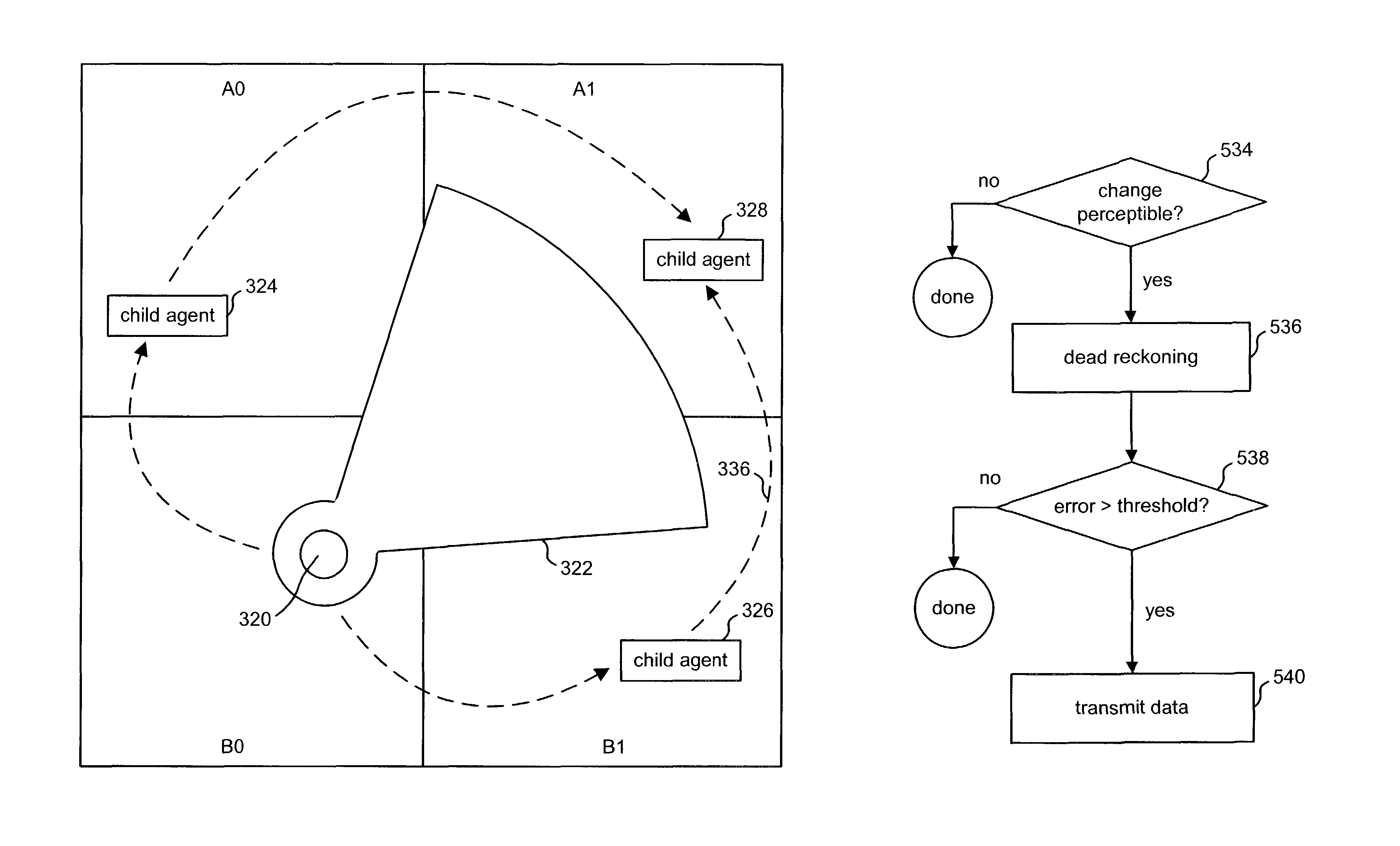
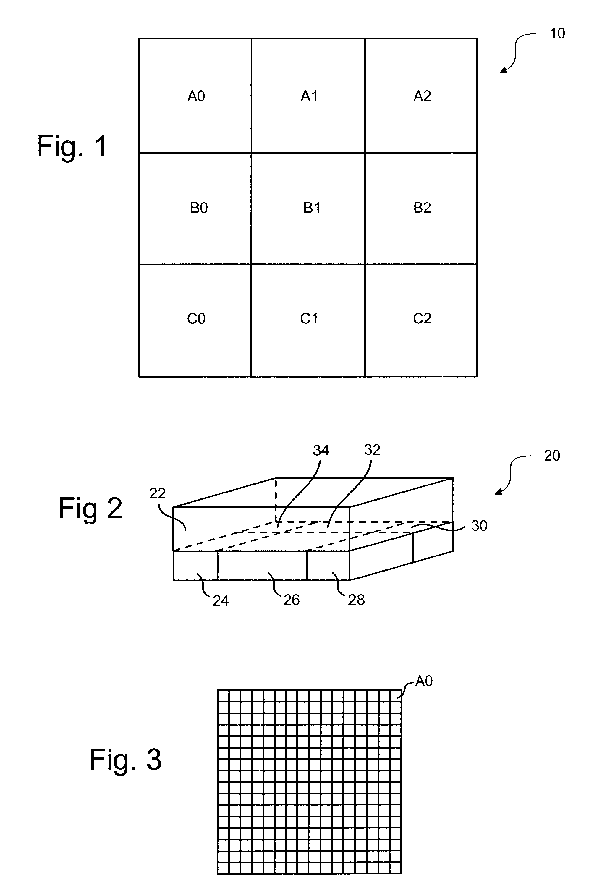
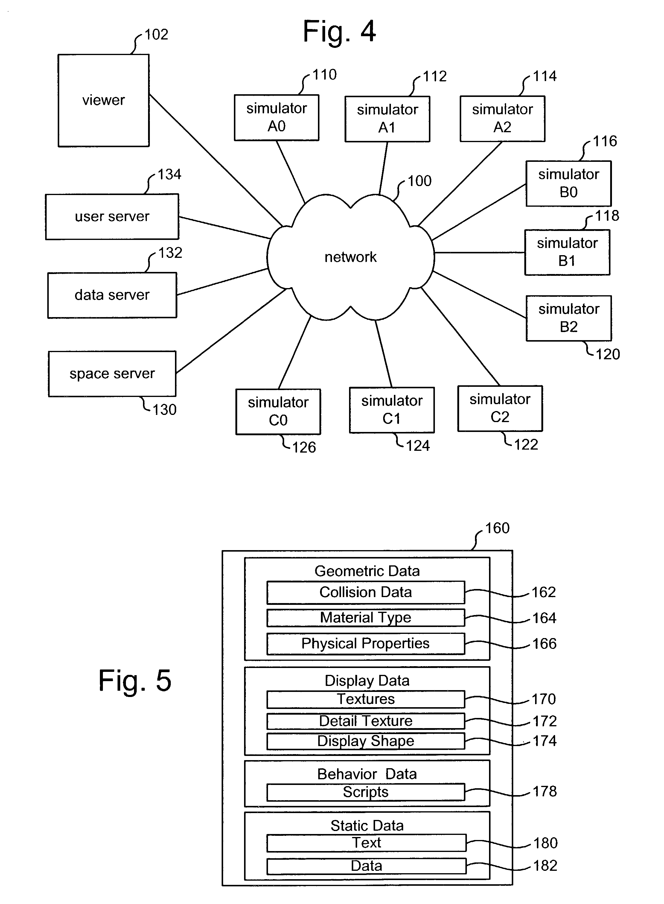
[0050]One embodiment of the present invention partitions the simulation space into a set of regions so that each location in the simulation space is located in a region. FIG. 1 shows simulation space 10 divided into nine regions, A0, A1, A2, B0, B1, B2, C0, C1, and C2. FIG. 1, which depicts a top view of the three dimensional simulation space 10, shows the r...


PUM


Abstract

Distributed continuous simulation of a three dimensional simulation space is provided using a set of simulation servers. The simulation space is partitioned into a set of regions. In one embodiment, each simulation server is responsible for simulating one of the regions of the simulation space. Users interacting with the simulation communicate directly with the simulation server responsible for simulating the region that the user is currently interacting with.

Description

[0001]This application claims the benefit of U.S. Provisional Application No. 60 / 371,743, entitled, “Simulation of a Large Virtual Space Using A Distributed Network,” filed on Apr. 11, 2002, incorporated herein by reference.BACKGROUND OF THE INVENTION[0002]1. Field of the Invention[0003]The present invention is directed to a simulation system.[0004]2. Description of the Related Art[0005]A common type of interactive computer experience is the simulation. In its most general sense, a simulation is the imitative representation of the functioning of a system or process. In many cases, a user is presented with a representation of some experience, such as performing an activity. There are many types of simulators. One well known example is a flight simulator, in which a user interacts with a computer that provides the user with a visual experience of flying an aircraft. Simulators can be used for training, research, entertainment, education, as well as many other suitable activities.[0006...

Claims


Application Information

Patent Timeline
Patent Type & Authority Patents(United States)
IPC IPC(8): G06F17/50G06T15/00
CPCG06F17/5009G06F30/20
Inventor ROSEDALE, PHILIP E.ONDREJKA, CORY R.MEADOWS, ANDREW L.
Owner LINDEN RES
Learn More