Piezoelectric element, and piezoelectric actuator and vibration wave motor including piezoelectric element

a piezoelectric element and actuator technology, applied in piezoelectric/electrostrictive/magnetostrictive devices, piezoelectric/electrostriction/magnetostriction machines, electrical apparatus, etc., can solve the problems of affecting the controllability and rotational position accuracy, and affecting the production efficiency of piezoelectric actuators. , to achieve the effect of more preferred mechanical properties and manufactured at lower cos

Active Publication Date: 2013-12-24
CANON KK +1
View PDF8 Cites 0 Cited by
  • Summary
  • Abstract
  • Description
  • Claims
  • Application Information

AI Technical Summary

Benefits of technology

[0034]In view of the above-mentioned problem, an object of the present invention is to provide a piezoelectric element, which can obtain more preferred mechanical property of a non-electrode portion of the piezoelectric element used for a vibration wave motor, and can be manufactured at lower cost, and also provide a piezoelectric actuator and a vibration wave motor that include the piezoelectric element.
[0038]According to the present invention, there can be obtained the piezoelectric element, which can obtain more preferred mechanical property of the non-electrode portion of the piezoelectric element used for a vibration wave motor, and can be manufactured at lower cost, and also the piezoelectric actuator and the vibration wave motor that include the piezoelectric element.

Problems solved by technology

This influence may cause deterioration of controllability and rotational position accuracy, and cause rotational unevenness, and further hinder even friction in the rod-like vibration wave motor of the conventional example.
There is another problem that the laminated piezoelectric element is expensive.
Palladium and platinum as precious metal are particularly expensive, and hence have a high cost ratio in the total cost of the electrode material, which is responsible for high cost.
Therefore, the increase in width of the non-electrode portion as described in Japanese Patent Application Laid-Open No. 2003-111450 does not always lead to a satisfactory output of the piezoelectric element.

Method used


Image

  • Piezoelectric element, and piezoelectric actuator and vibration wave motor including piezoelectric element
  • Piezoelectric element, and piezoelectric actuator and vibration wave motor including piezoelectric element
  • Piezoelectric element, and piezoelectric actuator and vibration wave motor including piezoelectric element

Examples


example 1

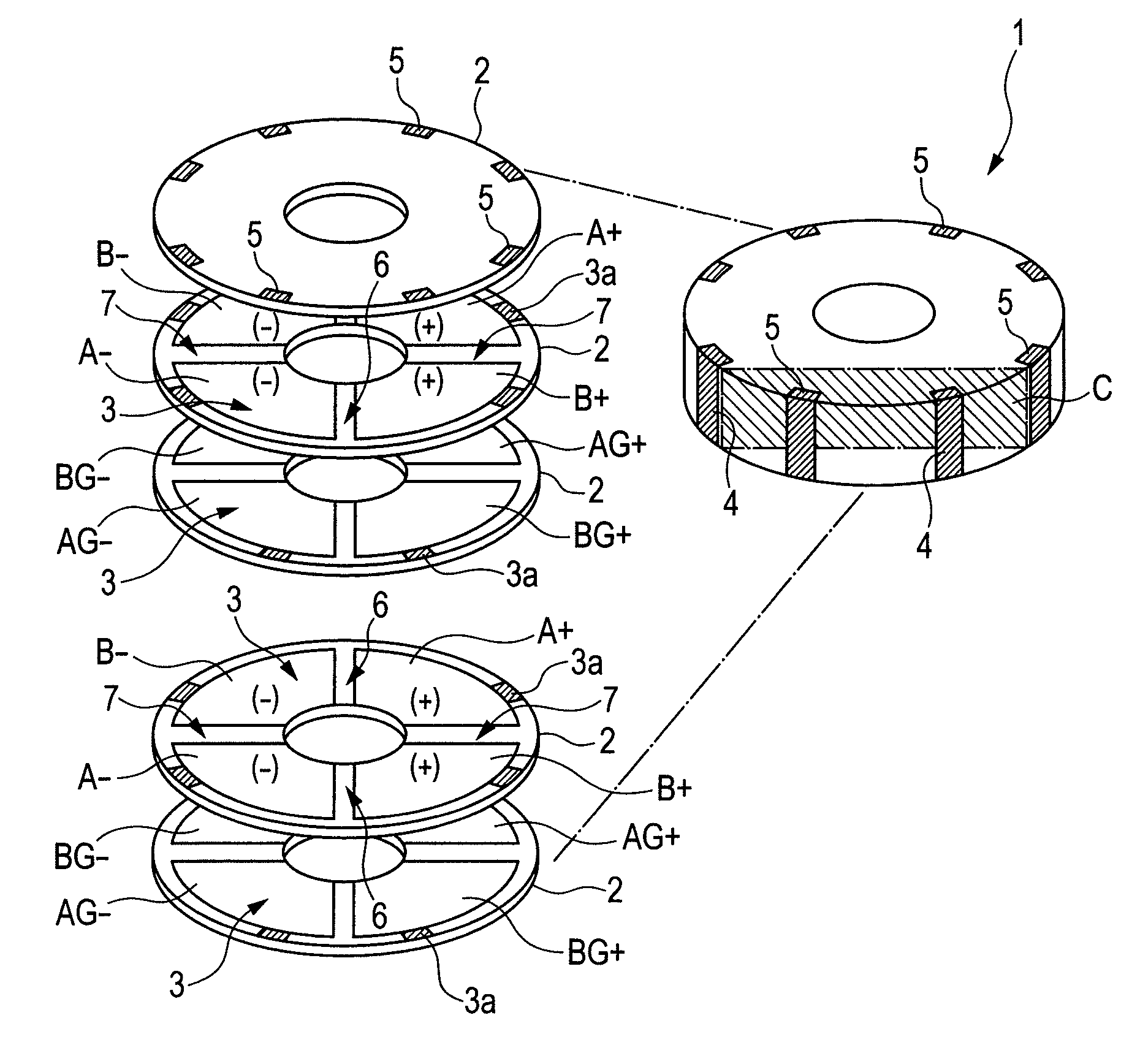
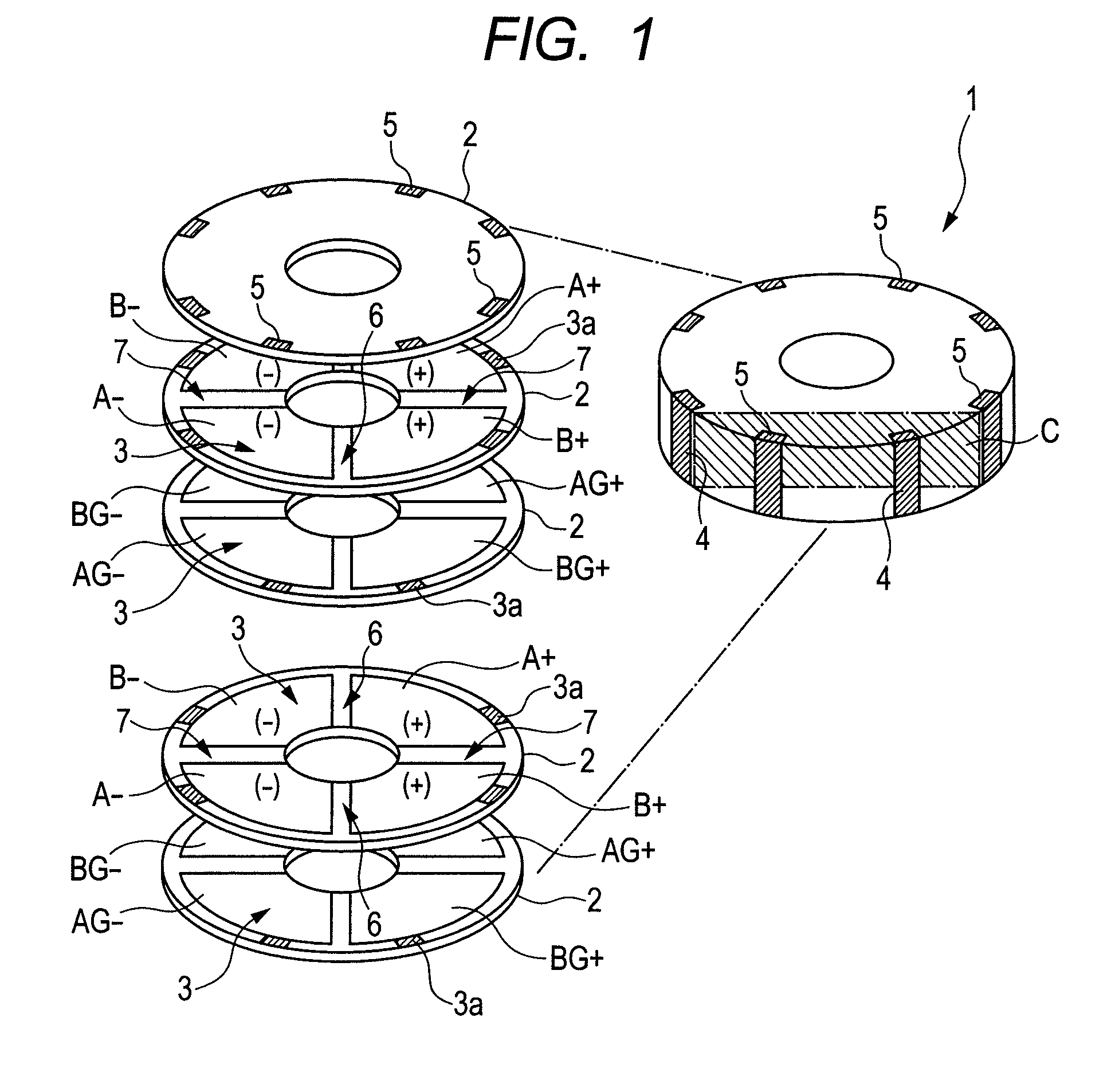
[0063]An example of a structure of the piezoelectric element to which the present invention is applied is described with reference to FIG. 1.

[0064]The present invention is different from the conventional example in composition of the piezoelectric material described later, manufacturing method therefor, and baking temperature. In addition, a mixing ratio of silver and palladium of the electrode material is also different.

[0065]Note that, in the following description, the baking temperature means the highest baking temperature in the baking process.

[0066]In FIG. 1, multiple electrode layers 3 are disposed on the surfaces of multiple piezoelectric layers 2 constituting a laminated piezoelectric element 1.

[0067]The electrode layer 3 is disposed so that its outer periphery is inside of the outer periphery of the piezoelectric layer 2 and is divided into four regions on the piezoelectric layer 2 (in FIG. 1, eight types of A+, A−, B+, B−, AG+, AG−, BG+, and BG− are illustrated).

[0068]The ...

example 2

[0143]As Example 2 of the present invention, a structural example of a laminated piezoelectric element 1′ according to another form different from Example 1 is described below with reference to FIGS. 7A and 7B.

[0144]FIG. 7A is an exploded perspective view of the laminated piezoelectric element 1′, and FIG. 7B is a cross sectional view taken along the arrow line in FIG. 7A.

[0145]The material composition of the piezoelectric material, the manufacturing method therefor, and the baking temperature are the same as those of Example 1. The laminated piezoelectric element 1′ is different from the laminated piezoelectric element 1 of Example 1 in two points.

[0146]One point is that an electrode layer 3′ formed on a piezoelectric layer 2′ is exposed to the outer periphery, and there is a non-electrode portion at an inner circumference portion.

[0147]The other point is that the electrical connection among electrode layers 3′ is obtained using eight through holes 5′ filled with conductive materia...

example 3

[0160]As described above, the test piece Tb supposing the non-electrode portion of Example 1 illustrated in FIG. 5 is not densified completely until the temperature becomes 960° C. unlike the test piece Ta that is the laminated piezoelectric element. However, even in the single plate piezoelectric ceramics (single layer type piezoelectric ceramics) made of a so-called single piezoelectric layer like the test piece Tb, it is preferred that baking be performed at a lower temperature. Therefore, as Example 3 of the present invention, a method for enabling baking of the single plate piezoelectric ceramics like the test piece Tb at a lower temperature is described below with reference to FIGS. 8A, 8B, and 8C.

[0161]FIG. 8A illustrates a test piece Tb′ before baking, which includes the test piece Tb of Example 1 and electrodes 3Tb′ that are electrode layers formed by printing and applying the electrode material paste containing silver at 95 wt % and palladium at 5 wt % used in Example 1 on...


PUM


Abstract

Provided is a piezoelectric element including: an electrode portion including a piezoelectric layer and an electrode layer that are laminated; and a non-electrode portion that is in contact with the electrode portion and includes a piezoelectric layer without an electrode layer, in which the non-electrode portion includes a region having a density smaller than a density of the piezoelectric layer of the electrode portion.

Description

BACKGROUND OF THE INVENTION[0001]1. Field of the Invention[0002]The present invention relates to a piezoelectric element having an electromechanical energy conversion function, in which piezoelectric layers and electrode layers are laminated, and more particularly, to a piezoelectric element suitable for a vibration wave motor and a piezoelectric actuator, and to a piezoelectric actuator and a vibration wave motor which include the piezoelectric element.[0003]2. Description of the Related Art[0004]A piezoelectric material is a typical material having an electromechanical energy conversion function for converting electrical energy into mechanical energy.[0005]Owing to its characteristics, a piezoelectric element made of a piezoelectric material is used in various piezoelectric actuators such as a vibration wave motor.[0006]In particular, in recent years, not only a single plate piezoelectric element but also laminated piezoelectric elements are used, such as an element in which multi...

Claims


Application Information

Patent Timeline
Patent Type & Authority Patents(United States)
IPC IPC(8): H01L41/08
CPCH01L41/0471H01L41/0835H02N2/106H01L41/273H10N30/871H10N30/505H10N30/053
Inventor MARUYAMA, YUTAKASHIMADA, AKIRAINADA, YUTAKAMATSUMOTO, MASASHIITOU, YUU
Owner CANON KK
Why Eureka
Try Eureka