Method for controlling side guides of a metal strip

a technology of lateral guide and metal strip, which is applied in the direction of metal-working feeding devices, roll mill control devices, manufacturing tools, etc., can solve the problems of reducing the braking effect of the strip, reducing the amount of energy needed to transport the strip, and no longer being able in all cases to adjust the strip, so as to achieve considerably improved automatic control of the system, the effect of significantly improving the influence of the guidance and prolonging the maintenance interval

Active Publication Date: 2013-12-31
SMS DEMAG AG
View PDF20 Cites 6 Cited by
  • Summary
  • Abstract
  • Description
  • Claims
  • Application Information

AI Technical Summary

Benefits of technology

[0007]The above technical goal is achieved by the inventive method for the automatic control of the lateral guide for a metal strip, especially at the entrance or exit of rolling stands or in front of drive apparatus, wherein the lateral guides comprise two straightedges, one arranged along each side of the metal strip; wherein the straightedges can be moved independently of each other; wherein the first straightedge is operated under automatic position control and the second straightedge under automatic force control; and wherein the forces of the metal strip acting on the first and the second straightedges are measured. According to the invention, furthermore, the nominal force of the second, force-controlled straightedge is prespecified as a function of the measured force acting on the first, position-controlled straightedge, wherein, as the force on the first, position-controlled straightedge increases, the nominal force for the second, force-controlled straightedge is decreased and / or, as the force on the first, position-controlled straightedge decreases, the nominal force for the second, force-controlled straightedge is increased. Because both straightedges are operated separately by automatic control circuits, namely, in the one case by a position-control circuit and in the other by a force-control circuit, the influence on the guidance is considerably improved. Because the nominal forces prespecified for the second straightedge are prespecified as a function of the forces measured on the first straightedge and not simply defined by material parameters alone or by an operator, the automatic control of the system is considerably improved. Less damage occurs because of the lower contact forces between the straightedges and the strip. Longer maintenance intervals and better strip quality result from the features of the inventive method. In addition, the braking effect on the strip is reduced, which decreases the amount of energy needed to transport the strip. The situation in which both the strip and the action of the force-controlled side press against the position-controlled side is also prevented. In particular, this also means that, when changes occur in the width of the strip, the straightedges can be adjusted more effectively to the widening or narrowing strip, as a result of which strips of this type can be guided more effectively and damage can be reduced.
[0008]In a preferred embodiment of the invention, the nominal force for the second, force-controlled straightedge is decreased to a prespecifiable, lower limit. As a result of this prespecifiable lower limit, it is possible in particular to ensure that the friction of the guiding straightedge is overcome. If the nominal force were to be set too low, it would no longer be possible in all cases to adjust the strip despite the tightening of the straightedge against the strip on the force-controlled side. Establishing a lower force limit thus makes it possible to improve the effectiveness of the automatic control.
[0010]In another preferred embodiment of the method, the parameter a gives a prespecifiable minimum force on the first, position-controlled straightedge. The prespecifiable parameter c, furthermore, gives the ratio of the relief of the second, force-controlled straightedge in the case of an increase in the force on the first, position-controlled straightedge. The parameter d represents the lower force limit, i.e., the limit below which the force may not fall when the nominal force for the second, force-controlled straightedge is being decreased. The quality of the control can be further improved through the appropriate choice of these parameters, which will be based on the concrete application or the on the existing mill.
[0011]In another preferred exemplary embodiment of the method, the forces measured at the first, position-controlled straightedge are filtered through a low-pass filter. Filtering with a low-pass filter filters out the high frequencies such as those caused by a disturbance; this results in a further improvement or further stabilization of the control. The control and in particular the specification of the nominal force value of the second, force-controlled straightedge thus also become insensitive to short-term fluctuations in the measured actual forces on the position-controlled side.
[0015]In another preferred embodiment of the method, the force acting on the first or second straightedge is determined on the basis of the measured electrical variables of the linear motor. Such measurement or determination simplifies the automatic control process.

Problems solved by technology

In addition, the braking effect on the strip is reduced, which decreases the amount of energy needed to transport the strip.
If the nominal force were to be set too low, it would no longer be possible in all cases to adjust the strip despite the tightening of the straightedge against the strip on the force-controlled side.

Method used


Image

  • Method for controlling side guides of a metal strip
  • Method for controlling side guides of a metal strip
  • Method for controlling side guides of a metal strip

Examples


Embodiment Construction

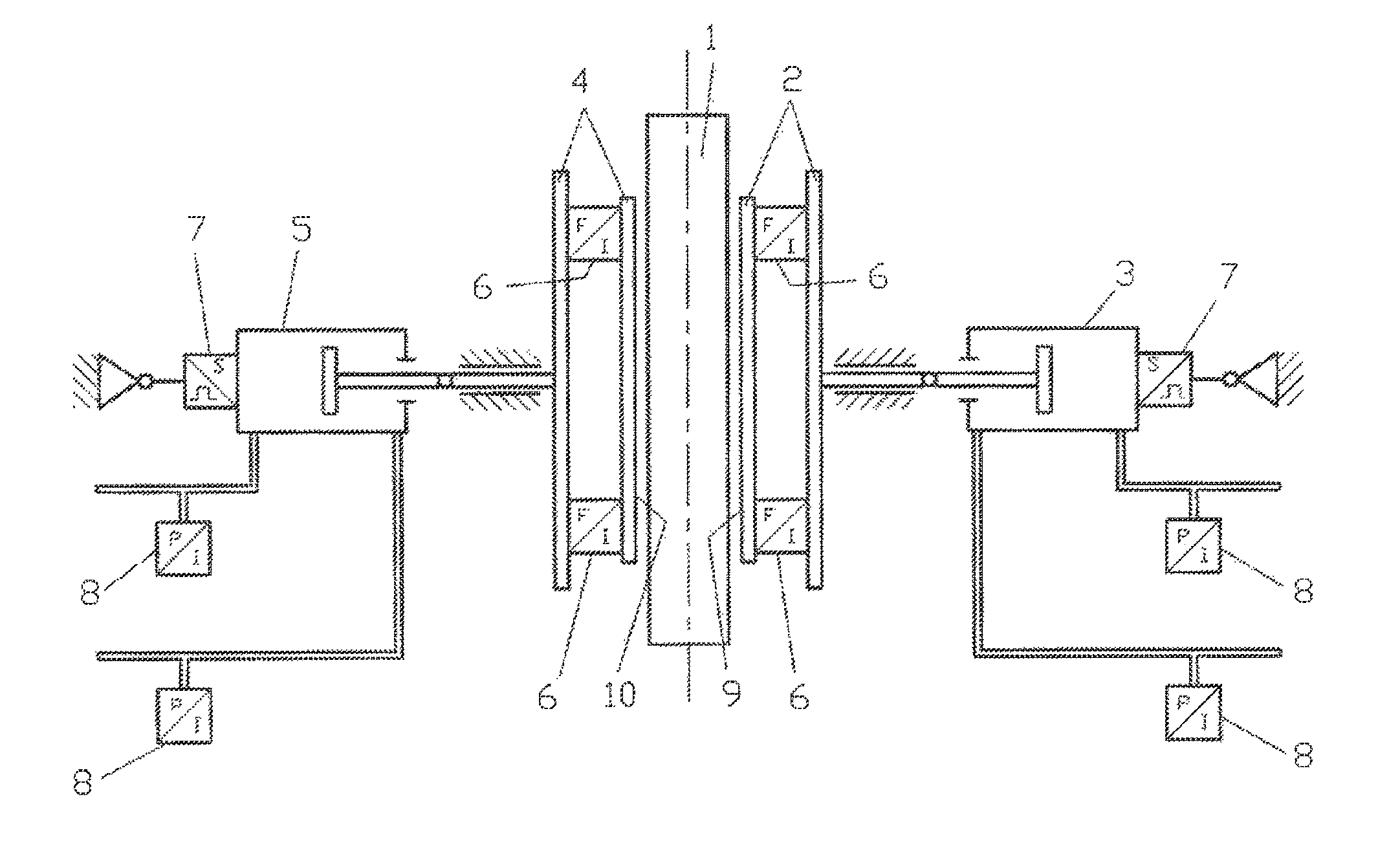
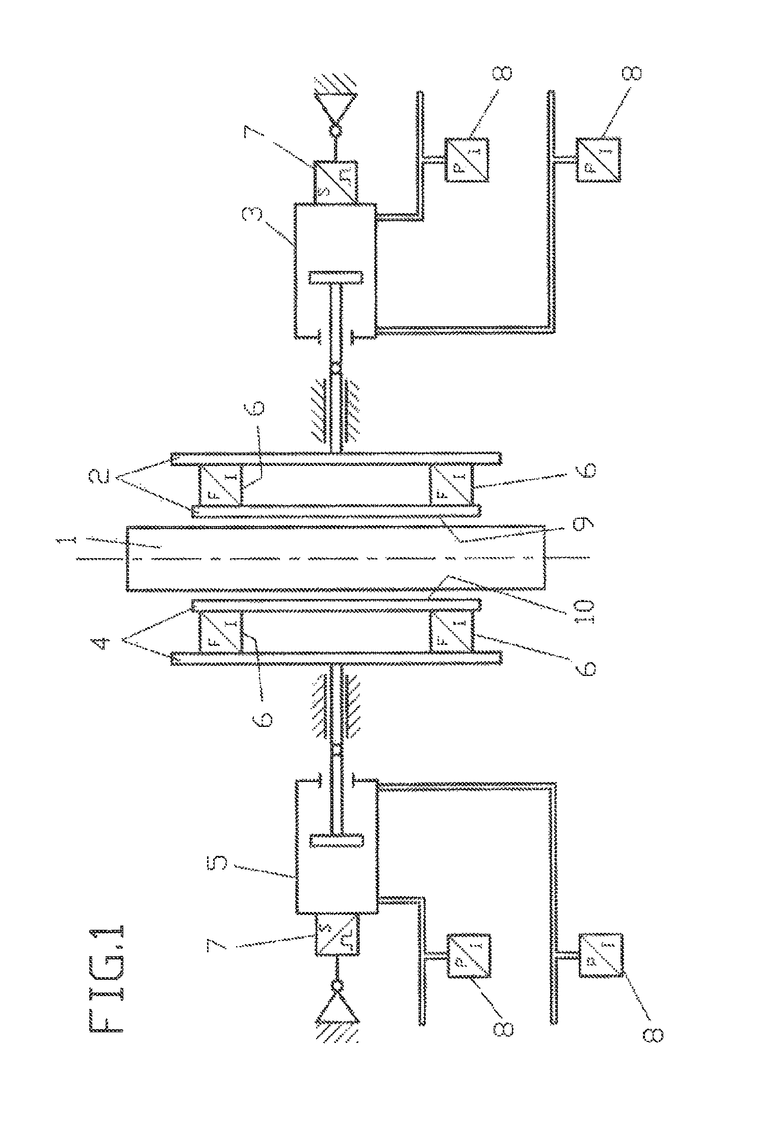
[0021]FIG. 1 shows an example of an arrangement for implementing the inventive method. A metal strip 1, preferably a steel strip 1, is guided on both sides, i.e., both long sides, by lateral guides. Each of these lateral guides, which are known in themselves, comprises a straightedge 2, 4. The metal strip 1 can be contacted by the guide edges 9, 10 of the straightedges 2, 4. The straightedges 2, 4 are preferably pressed laterally against the strip 1 by drives or pressing devices 3, 5. As shown in FIG. 1, it is also possible as an option to provide force-measuring sensors 6 between the guide edges 9, 10 and the drives or pressing devices 3, 5 of the straightedges 2, 4. It is also possible for the straightedges 2, 4 to consist of several parts, as shown. The pressing devices 3, 5 can be formed , as shown by way of example, by hydraulic or pneumatic cylinders. Position sensors 7 are also provided according to FIG. 1; these sensors can measure the distance traveled by the pistons in the...


PUM

PropertyMeasurementUnit
forcesaaaaaaaaaa
forceaaaaaaaaaa
pressing forceaaaaaaaaaa

Abstract

The invention relates to a method for controlling a side guide of a metal strip (1), in particular in the inlet or outlet of roll stands or driving apparatuses, wherein the side guide comprises a guide (2, 4) disposed laterally to the metal strip (1) on both sides of the metal strip (1), and the guides (2, 4) can be displaced independently of each other. One of the guides (2) is thereby driven by means of position control, and a second of the guides (4) is driven by means of force control, wherein forces of the metal strip (1) acting on the first guide (2) and the second guide (4) are measured. The target force for the second, force-controlled guide (4) is thereby prescribed as a function of the measured force on the first, position-controlled guide (2), wherein as the force on the first, position-controlled guide (2) increases, the target force for the second, force-controlled guide (4) is reduced. In particular, damage to the guides (2, 4) and to the metal strip (1) can be prevented or at least reduced by means of said type of controlling.

Description

[0001]The present application is a 371 of International application PCT / EP2010 / 070698, filed Dec. 23, 2010, which claims priority of DE 10 2009 060 823.0, filed Dec. 29, 2009, the priority of these applications is hereby claimed and these applications are incorporated herein by reference.BACKGROUND OF THE INVENTION[0002]The invention pertains to a method for controlling the lateral guides for a metal strip, especially at the entrance or exit from rolling stands in rolling mills, for example; they can also be used in front of drive apparatus or in other strip processing lines.[0003]Methods for automatically controlling the lateral guides for a metal strip are already known from the prior art. Such guides usually consist of two straightedges, one on each side of the strip, which are positioned by hydraulic cylinders and which can be pressed or tightened against the strip as the strip passes by. The known systems frequently also comprise a mechanical connection between the two straight...

Claims


Application Information

Patent Timeline
Patent Type & Authority Patents(United States)
IPC IPC(8): B21B37/00
CPCB21C47/34B21D43/023B21B39/14B21C47/3416B21B37/68B21D43/02
Inventor TUSCHHOFF, MATTHIAS
Owner SMS DEMAG AG
Why Eureka
Try Eureka