Turbomachine foot unit

a technology for turbomachines and foot units, which is applied in the direction of machine supports, furniture parts, liquid fuel engines, etc., can solve the problems of fatigue of the foot unit or the foot unit of the turbomachine, and the danger of fatigue in the secure attachment of the bas

Active Publication Date: 2013-12-31
SIEMENS ENERGY GLOBAL GMBH & CO KG
View PDF17 Cites 11 Cited by
  • Summary
  • Abstract
  • Description
  • Claims
  • Application Information

AI Technical Summary

Benefits of technology

[0008]The invention in this case proceeds from the consideration that a turbomachine becomes hot while it is in operation, the heat being distributed unevenly in the volume of the turbomachine. For example, in the case of an air compressor, the air compressed to an increasingly greater extent from stage to stage becomes warmer, so that the turbomachine is relatively cool at the air inlet and is hot at the outlet of the compressed air. As a result of the heat, the turbomachine as a whole expands, with the result that stresses and deformations are transferred to feet fixed firmly to the base. In the case of a frequent change in temperature of the turbomachine, the feet or the foot unit of the turbomachine therefore experience fatigue, and because of this material fatigue is hazardous to secure fastening to the base. Owing to the movability of at least one of the feet in relation to the horizontal base or to a fastening means fixed to the base, the corresponding foot can participate in length compensation, so that the mechanical load on this foot is reduced, as compared with firmly fixed feet.
[0023]It is proposed, furthermore, that the turbomachine foot unit comprise a guide means fastened to the base, for restricting the horizontal movement of part of the turbomachine to one-dimensional movement. The guide means may be a center guide chock which serves as a radial fixed point for preventing a rotation of the turbomachine in the horizontal. A load on the shaft can be kept low.

Problems solved by technology

In the case of a frequent change in temperature of the turbomachine, the feet or the foot unit of the turbomachine therefore experience fatigue, and because of this material fatigue is hazardous to secure fastening to the base.

Method used


Image

  • Turbomachine foot unit
  • Turbomachine foot unit
  • Turbomachine foot unit

Examples


Embodiment Construction

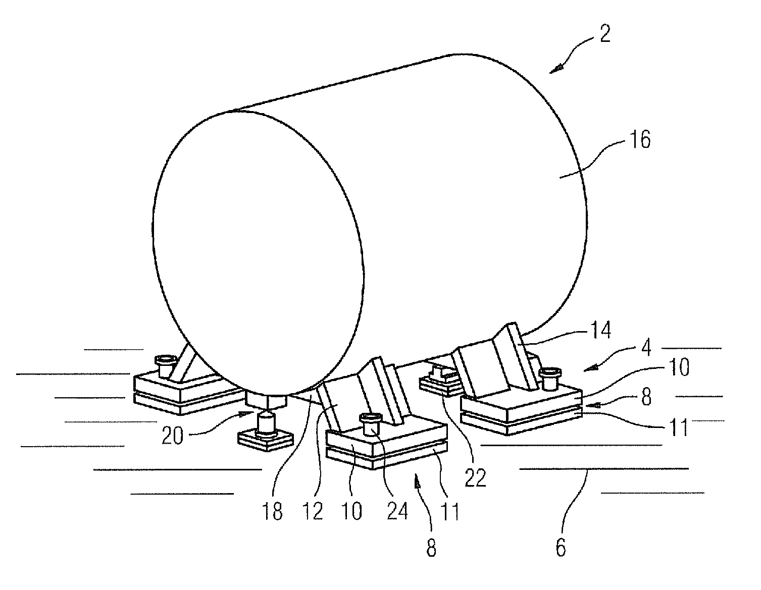
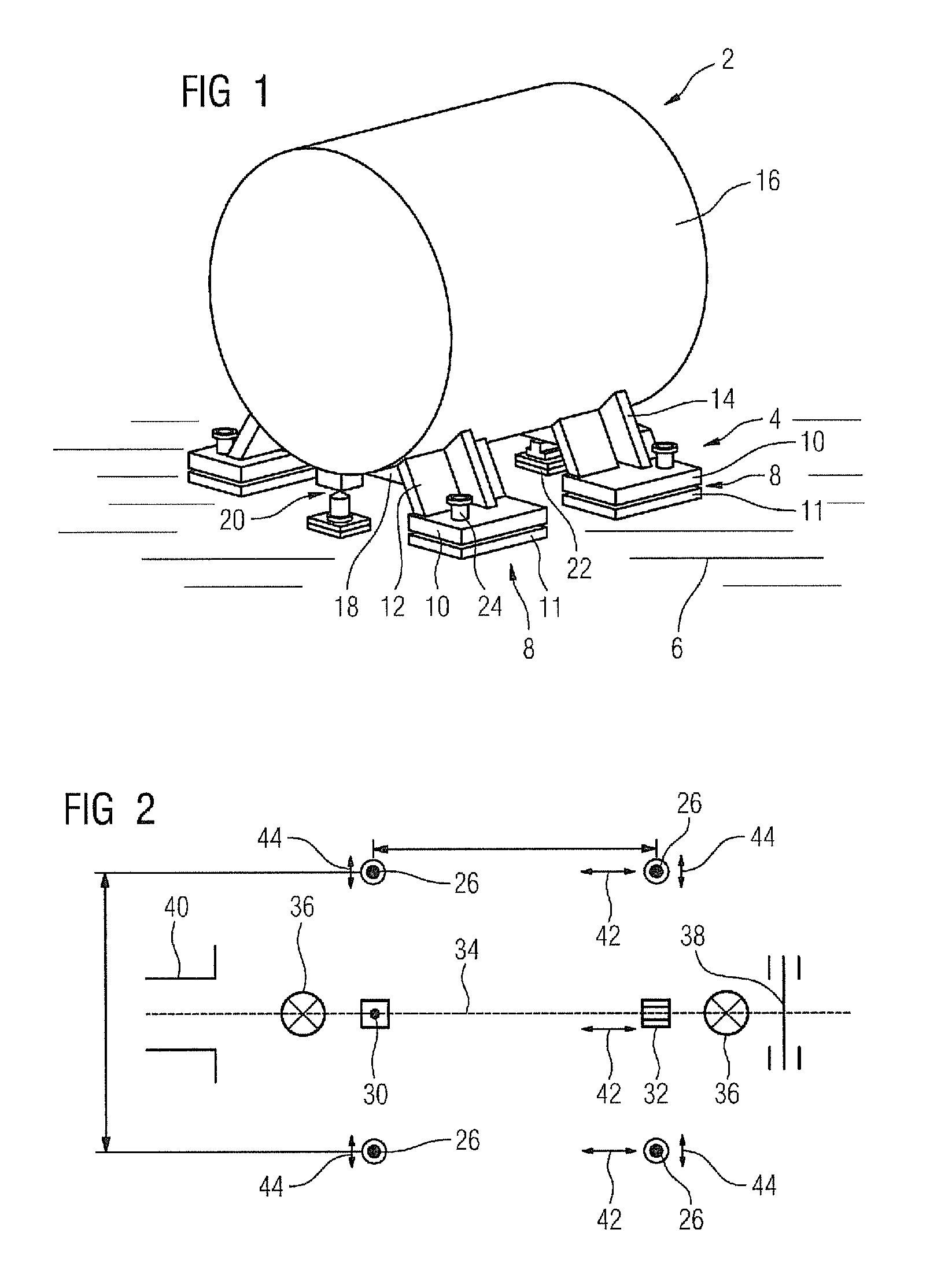
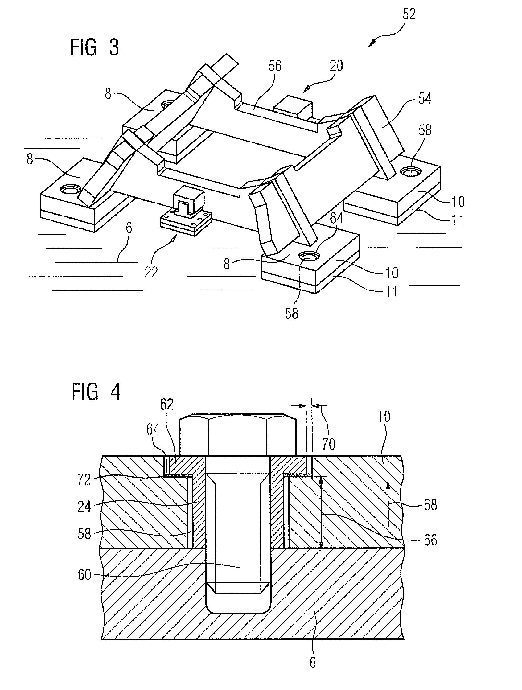
[0034]FIG. 1 shows a turbomachine 2 in a diagrammatic perspective illustration, with a turbomachine foot unit 4 which is welded to a housing 16 of the turbomachine 2. The turbomachine foot unit 4 stands on a base 6, indicated in FIG. 1, which extends horizontally and comprises a planar foundation and, on each foot 8, a foot plate 11. The turbomachine foot unit 4 comprises four feet 8, each with a foot plate 10 and with two foot panels 12, 14 which stand perpendicularly to one another and are welded to the housing 16 of the turbomachine 2. The two foot panels 12, 14 are welded to the foot plate 10 at their end lying opposite the turbomachine 2. In each case two feet 18 are connected to one another in each case via a transverse panel 18. It is likewise conceivable that in each case two foot panels 14 and one transverse panel 18 are produced in one piece and the foot panels 12 are in two parts and are welded to a foot panel 14 on both sides.

[0035]Moreover, FIG. 1 illustrates in the man...


PUM


Abstract

A turbomachine foot unit with a plurality of feet is provided. The plurality of feet is fastened to a turbomachine. The turbomachine stands upright on a horizontal base. The turbomachine foot includes fastening devices for fastening the feet to the base. At least one of the feet is mounted in a horizontally moveable manner relative to one of the fastening devices fastening the foot to the base.

Description

CROSS REFERENCE TO RELATED APPLICATIONS[0001]This application is the U.S. National Stage of International Application No. PCT / EP2009 / 067776 filed Dec. 22, 2009, and claims the benefit thereof. The International Application claims the benefits of German Patent Application No. 10 2008 064 371.8 DE filed Dec. 22, 2008. All of the applications are incorporated by reference herein in their entirety.FIELD OF INVENTION[0002]The invention relates to a turbomachine foot unit with a plurality of feet for fastening to a turbomachine and for standing the turbomachine on a horizontal base and with fastening means for fastening the feet to the base, with the turbomachine fastened on the base at least one of the feet being mounted so as to be horizontally movable in relation to one of the fastening means which fastens the foot to the base.BACKGROUND OF INVENTION[0003]Turbomachines for industrial purposes or in power stations are often connected to an electrical machine, for example a turbocompress...

Claims


Application Information

Patent Timeline
Patent Type & Authority Patents(United States)
IPC IPC(8): F16M7/00
CPCF04D29/605F01D17/165F05D2260/52F04D29/668F04D29/669F02C9/20F01D17/162F04D29/601F05D2230/64F01D25/28F02C6/12
Inventor HUTH, SEBASTIANMEYER, MARCUSZACHARIAS, WOLFGANG
Owner SIEMENS ENERGY GLOBAL GMBH & CO KG
Why Eureka
Try Eureka