Optical fiber management system and method

a technology of optical fiber and management system, applied in the direction of underwater equipment, transportation and packaging, special-purpose vessels, etc., can solve the problem of delay in the response of rovs, and achieve the effect of responding more quickly

Active Publication Date: 2013-12-31
GENERAL DYNAMICS MISSION SYST INC
View PDF10 Cites 12 Cited by
  • Summary
  • Abstract
  • Description
  • Claims
  • Application Information

AI Technical Summary

Benefits of technology

[0006]In another embodiment, a second optical fiber management system having a second spool of optical fiber can be mounted in a surface structure on or adjacent to a surface support ship. A sensor can detect the movement of the surface support ship and emit the optical fiber from the second spool at a rate that is approximately equal to or faster than the movement of the support ship through the water. As the ship moves, the optical fiber can be released from the second spool to minimize the tension in the fiber.
[0008]In an embodiment, the optical fiber management system can be controlled by the control signals transmitted to the ROV. If the ROV receives a signal to move in any direction, the optical fiber management system can determine the speed of the control signal and emit the optical fiber at the same or slightly faster rate. In this embodiment, the optical fiber management system can respond more quickly because it can emit the optical fiber when the movement control signal is received. There will be some delay in the ROV's response, so the optical fiber management system can emit the optical cable just before the ROV moves.
[0009]The optical cable can be removed from the spool and fed to an emitter that applies a tension to the optical cable so that it is removed from the spool without tangling. The emitter can apply a tension force that can be less than about 1 pound of force. For example, in an embodiment the emitter can apply an optical cable tension of about ½ to 1 ounce which can gently pull the optical fiber from the spool as it rotates but may not cause the optical fiber spool to rotate faster than the motor rotation.

Problems solved by technology

There will be some delay in the ROV's response, so the optical fiber management system can emit the optical cable just before the ROV moves.

Method used


Image

  • Optical fiber management system and method
  • Optical fiber management system and method
  • Optical fiber management system and method

Examples


Embodiment Construction

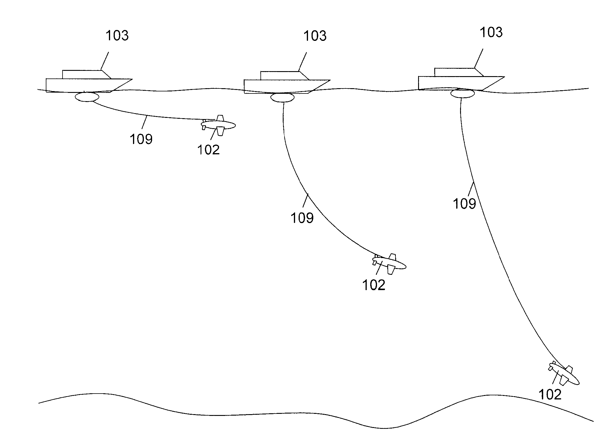
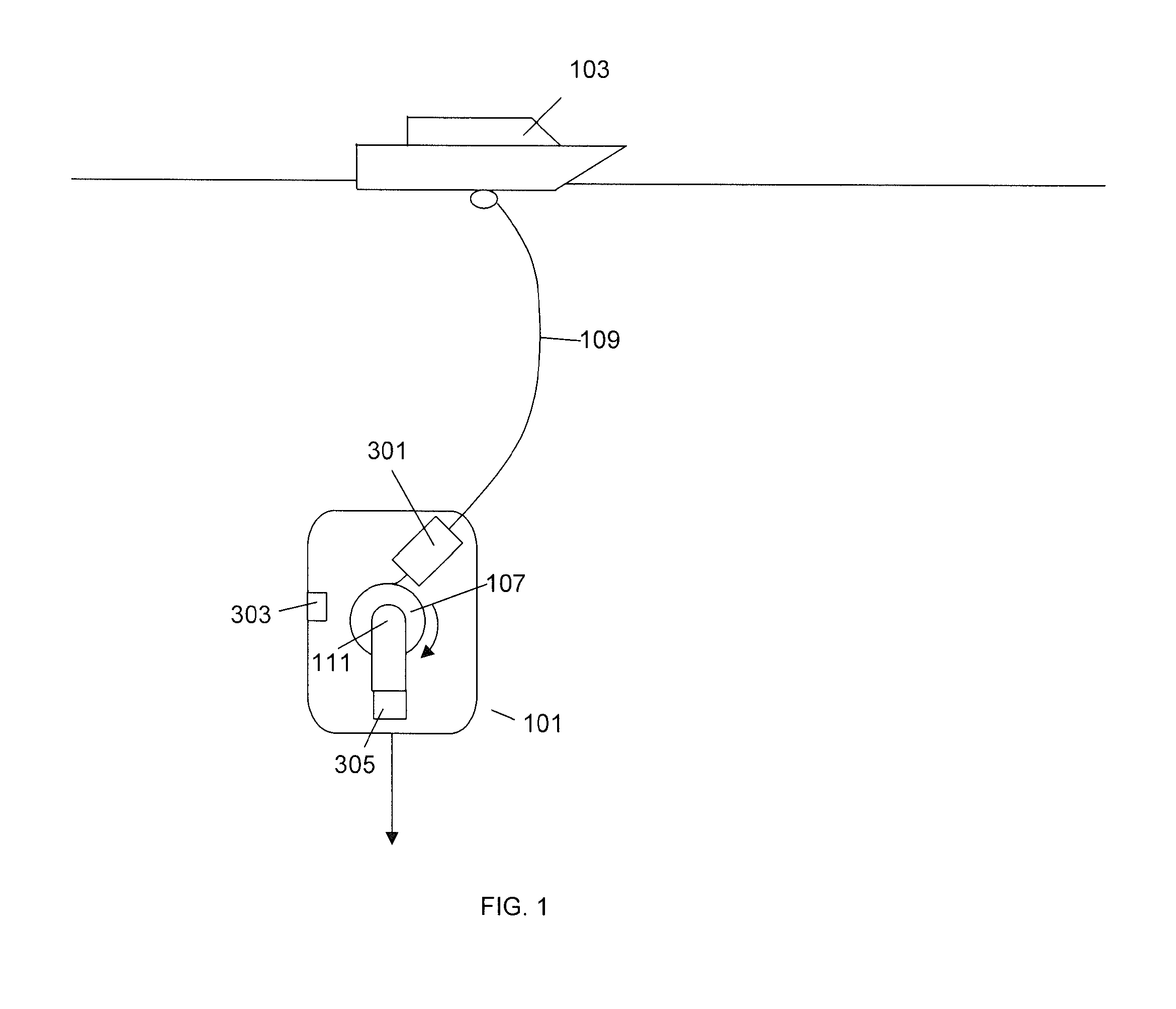
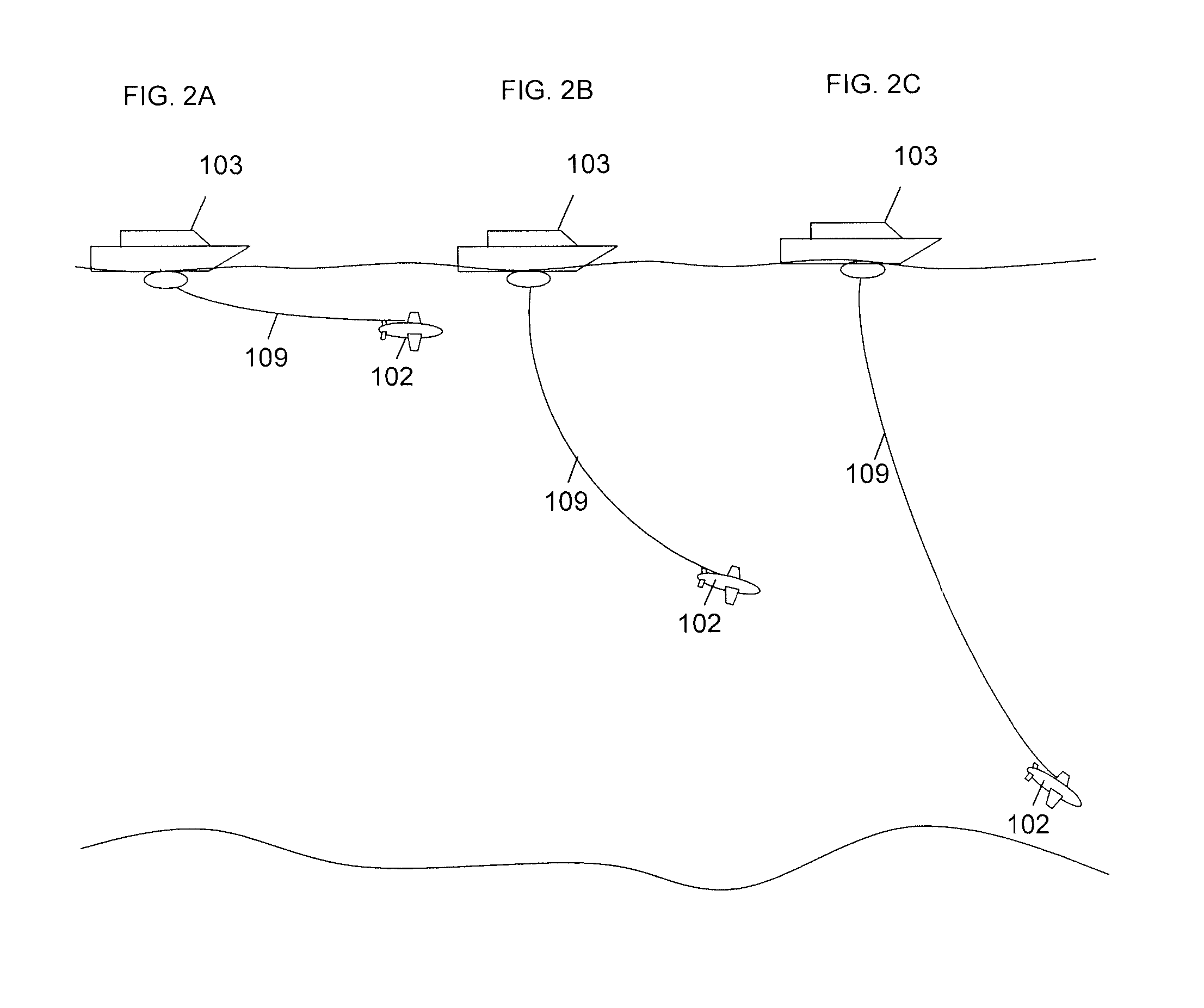
[0021]The present invention is directed towards a spool for storing a fiber for underwater applications. With reference to FIG. 1, in an embodiment, the fiber can be an optical fiber 109 that is stored on a spool 107 that is used for communications between a support ship 103 and a Remotely Operated Vehicle (ROV) 101. An end of the optical fiber 109 can be coupled to communications equipment on the support ship 103 and the other end of the optical fiber 109 can be coupled to communications and control equipment on the ROV 101.

[0022]The spool 107 of the optical fiber 109 is stored on the ROV 101. As the ROV 101 travels, the spool 107 can rotate which causes the optical fiber 109 to stream out of the ROV 101. The end of the optical fiber 109 can be coupled to a rotating coupling 111 so the spool 107 can rotate while maintaining communications between the ROV 101 and the support ship 103. In an embodiment, a sensor 303 can detect the relative velocity of the ROV 101 through the water an...


PUM


Abstract

An optical fiber management system for a remotely operated vehicle (ROV) includes a spool containing a length of optical cable, a motor coupled to the spool, a motor controller, a speed sensor and a feed mechanism. The motor controller can detect the speed of the ROV through water and control the rotational speed of the motor so that the optical cable is removed from the spool at a speed that is equal to or greater than the speed of the ROV. A feed mechanism is used to apply a tension to the optical cable so that it is removed from the spool and emitted from the ROV without becoming tangled.

Description

CROSS REFERENCE TO RELATED PATENT APPLICATIONS[0001]This patent application claims priority to U.S. Provisional Patent Application No. 61 / 345,985, Optical Fiber Management System, filed May 18, 2010. This application is also a continuation in part of U.S. patent application Ser. No. 12 / 793,589, Deployable Optical Fiber Cartridge, filed Jun. 3, 2010 and U.S. patent application Ser. No. 12 / 795,971, Ocean Deployable Biodegradable Optical Fiber Cable, filed Jun. 8, 2010. The contents of U.S. patent application Ser. Nos. 12 / 793,589, 12 / 795,971 and 61 / 345,985 are hereby incorporated by reference.FIELD OF INVENTION[0002]The application is directed towards a system for deploying an optical fiber from an optical fiber cartridge in underwater applications.BACKGROUND[0003]Fibers such as optical fibers have been used in underwater applications to transmit and receive information. For example, an underwater device can have a propulsion system and a direction control mechanism. The underwater dev...

Claims


Application Information

Patent Timeline
Patent Type & Authority Patents(United States)
IPC IPC(8): F16L1/12
CPCB65H75/4484B65H75/425B63G8/001B65H2701/32B65H51/16B63C11/52
Inventor HAWKES, GRAHAMCHIAU, CHARLES SWRIGHT, ADAM
Owner GENERAL DYNAMICS MISSION SYST INC
Why Eureka
Try Eureka