Detection of discontinuity densities in composite materials

a composite material and density detection technology, applied in the direction of optical radiation measurement, porous material analysis, suspensions, etc., can solve the problems of large size (the size of a refrigerator) and high cost of niche research apparatus

Active Publication Date: 2013-12-31
THE UNITED STATES OF AMERICA AS REPRESENTED BY THE SECRETARY OF THE NAVY
View PDF3 Cites 16 Cited by
  • Summary
  • Abstract
  • Description
  • Claims
  • Application Information

AI Technical Summary

Problems solved by technology

The technology began to see first commercial development later that decade with very larg

Method used


Image

  • Detection of discontinuity densities in composite materials
  • Detection of discontinuity densities in composite materials
  • Detection of discontinuity densities in composite materials

Examples


Embodiment Construction

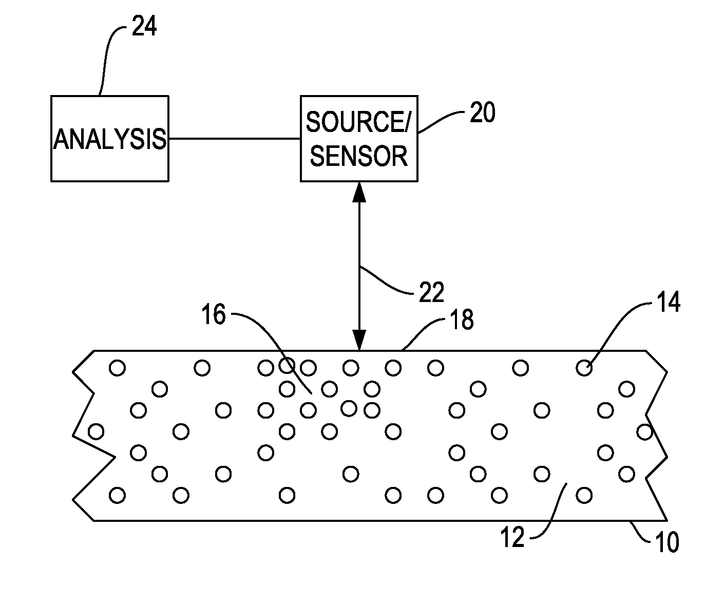
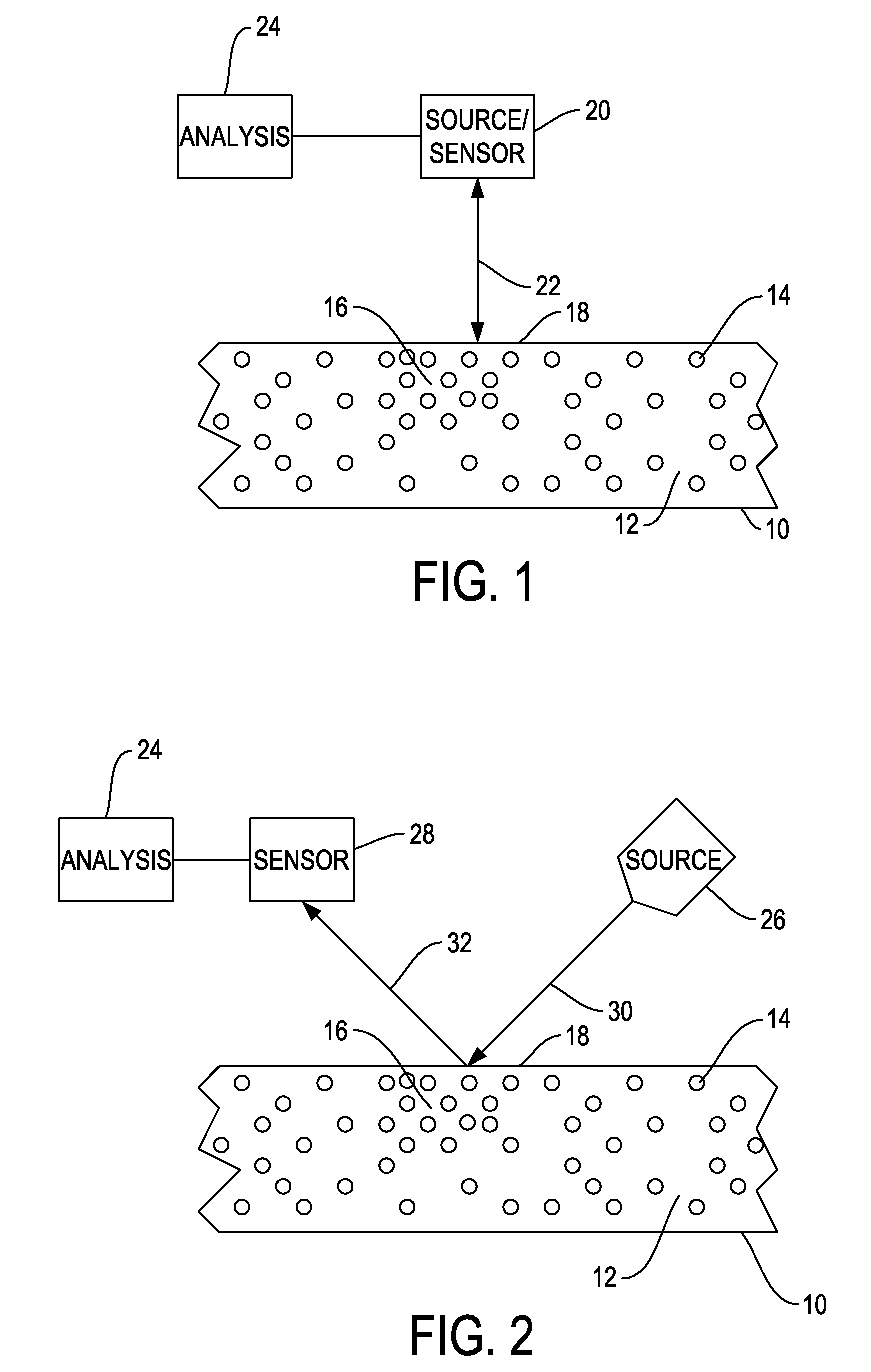
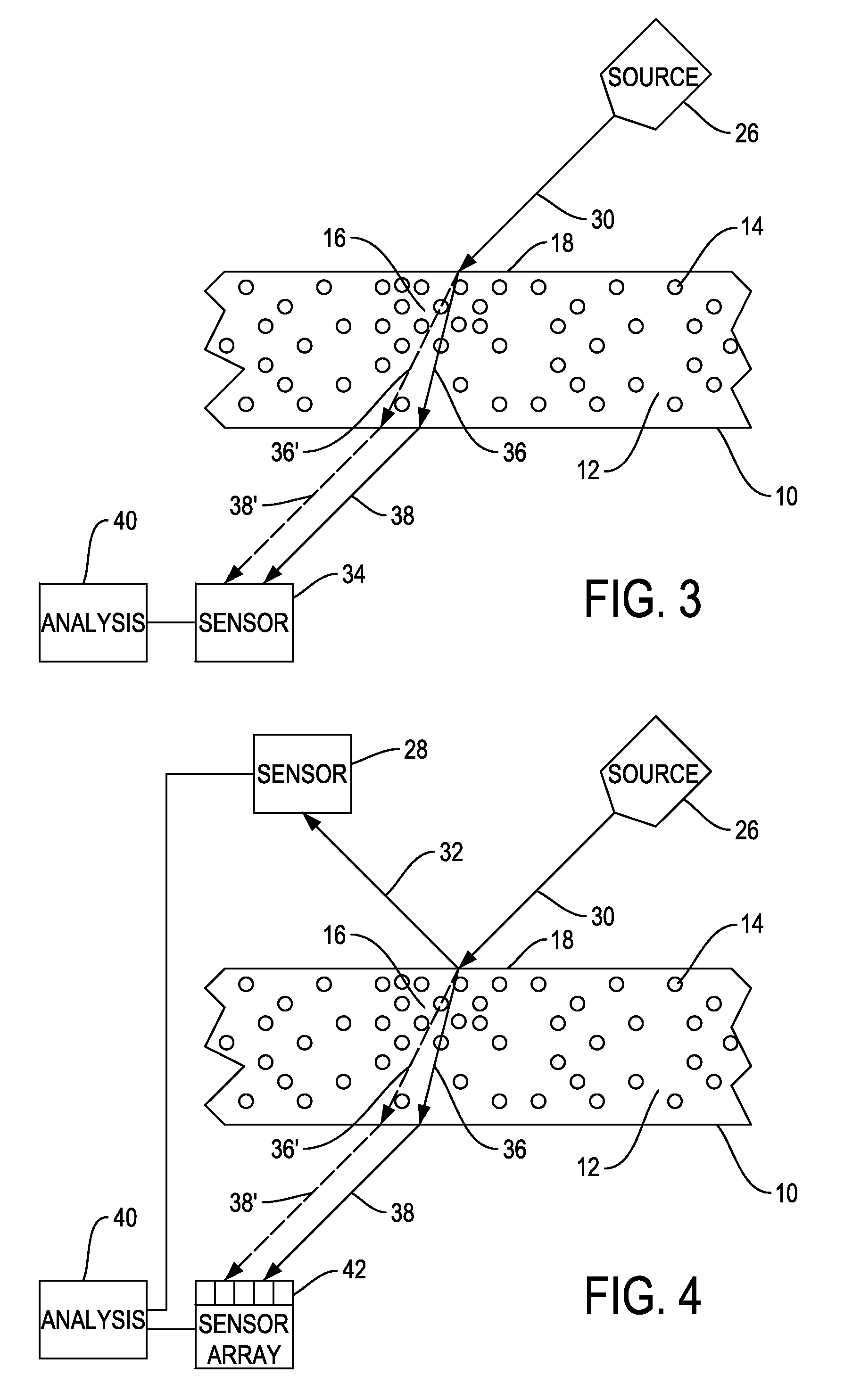
[0022]FIGS. 1-4 show embodiments of the invention with reference to a test sample 10. Reference numbers for the test sample are the same throughout. Test sample 10 is shown in cross-section. It includes a substrate 12 having micro-inclusions 14 suspended therein. Test sample 10, substrate, and micro-inclusions 14 are not shown to scale. In actual use, micro-inclusions 14 will be much smaller and present at a much greater concentration. Region 16 of sample 10 has a micro-inclusion gradient having many more micro-inclusions 14 at a surface 18 of the sample 10. While application of this technology is particularly applicable to micro-inclusions dispersed in a polymer matrix, it is equally applicable to any group of material agglomerates in suspension in a bulk material where the agglomerates are intended to be arranged with a certain uniformity, absence of uniformity, or gradient.

[0023]A gradient in micro-inclusion concentration can be detected by its effect on electromagnetic waves ref...


PUM


Abstract

A method for detecting suspended discontinuity densities in a material is provided. The method includes transmitting terahertz electromagnetic radiation toward a surface of the material. This radiation is received at an expected location after interacting with the material. The power level of the received radiation is measured and deviation from the expected value is used to determine a suspended discontinuity density gradient in the material. The method can be used with either reflected radiation or transmitted radiation. Embodiments of the method can calculate the index of refraction in the material and correlate this with the suspended discontinuity density of the material.

Description

STATEMENT OF GOVERNMENT INTEREST[0001]The invention described herein may be manufactured and used by or for the Government of the United States of America for governmental purposes without the payment of any royalties thereon or therefor.CROSS REFERENCE TO OTHER PATENT APPLICATIONS[0002]None.BACKGROUND OF THE INVENTION[0003](1) Field of the Invention[0004]The present invention is directed generally towards a non-destructive method for detecting densities of components of a composite material (referred to herein as discontinuity densities and suspended discontinuity densities). More specifically it is directed toward determining micro-inclusion gradients and micro-inclusion gradient boundaries in micro-inclusion-impregnated materials utilizing sub-centimeter wavelength electromagnetic radiation. This method also detects micro-inclusion concentration levels in micro-inclusion-impregnated materials in a nondestructive, contactless fashion.[0005](2) Description of the Prior Art[0006]Ter...

Claims


Application Information

Patent Timeline
IPC IPC(8): G01J5/02
CPCG01N21/3581G01N2015/0061G01J5/02G01N2015/0693G01N15/06G01N15/00
Inventor LOCKHART, PATRIC, K.
Owner THE UNITED STATES OF AMERICA AS REPRESENTED BY THE SECRETARY OF THE NAVY
Why Eureka
Try Eureka