
Combined background and 20/40 coexistence scan

a background and coexistence scan technology, applied in the field of scanning mechanisms in wireless networks, can solve problems such as tight 5 mhz spacing between the eleven channels, insufficient free channels left for other devices, and inability to solve tight background scans, so as to reduce the number of scans, reduce power consumption, and increase data traffic throughput

Inactive Publication Date: 2013-12-31
QUALCOMM INC
View PDF6 Cites 2 Cited by
  • Summary
  • Abstract
  • Description
  • Claims
  • Application Information

AI Technical Summary

Benefits of technology

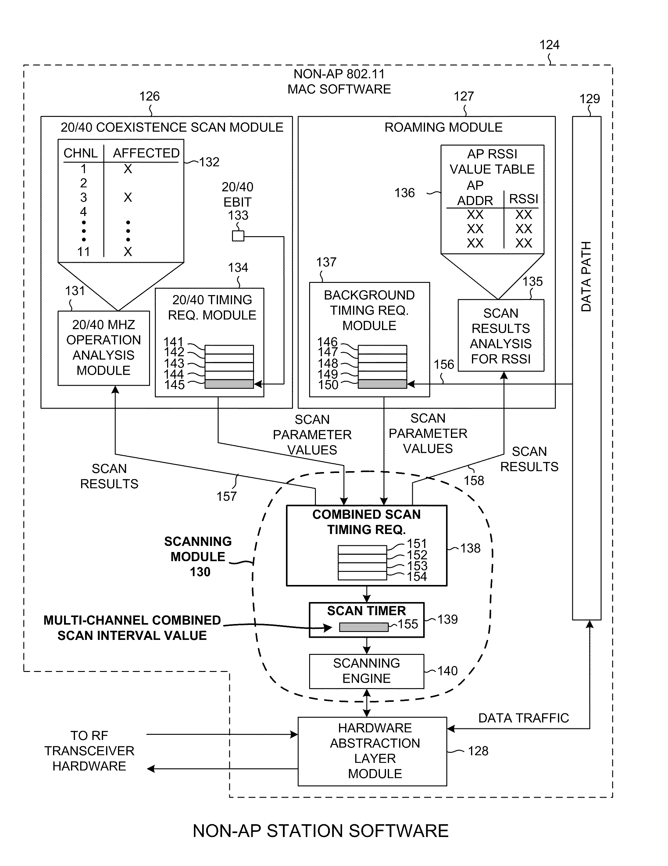
This patent describes a technology that reduces the number of scans performed by a non-AP station, such as a laptop, by using combined scans to obtain information from multiple channels or types of scans. Combining the scan parameter values allows the non-AP station to perform a multi-channel combined scan operation, resulting in increased data throughput, improved processing efficiency, and reduced power consumption. Additionally, this technology allows the non-AP station to determine the interval of time between scans, which further improves data throughput. By disabling unnecessary scanning operations and reducing processing load on the non-AP station, this technology improves overall network performance.

Problems solved by technology

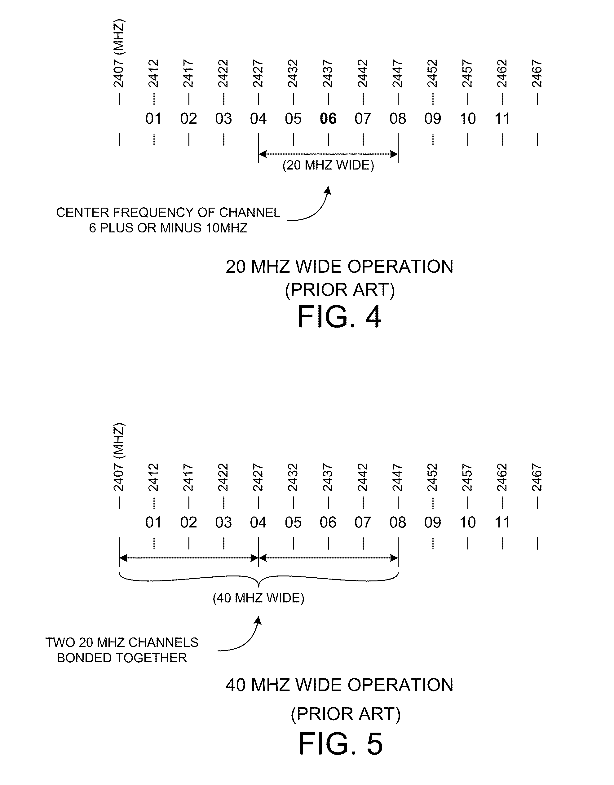
An AP station using wider 40 MHz channels, however, may cause operating problems for other devices that might be sharing the same 2.4 GHz band as the IEEE 802.11 devices.
Using wide 40 MHz channels may consume so many of the channels for the 802.11 devices that there may not be enough free channels left for use by other devices of other protocols that are trying to share the same 2.4 GHz band with the 802.11(n) devices.
Moreover, the tight 5 MHz spacing between the eleven channels may introduce problems.
Due to the closer spacing of channels, interference may occur between the non-802.11 devices and the 802.11 devices.
Accordingly, 20 / 40 scanning by the non-AP station is disabled because results of such 20 / 40 scanning would no longer be usable to affect operation of the AP station.

Method used


Image

  • Combined background and 20/40 coexistence scan
  • Combined background and 20/40 coexistence scan
  • Combined background and 20/40 coexistence scan

Examples


Embodiment Construction

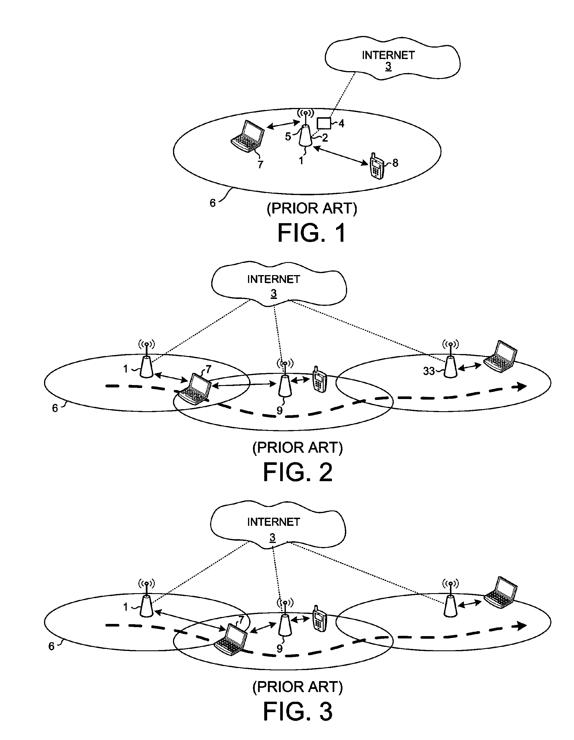
[0038]FIG. 9 is a simplified diagram of an IEEE 802.11(n) wireless network system 100 in accordance with one novel aspect. System 100 includes multiple IEEE 802.11(n) compliant Access Point stations (AP stations) 101-103 that are connected to a network 104. Network 104 may be a Local Area Network or another network, and may be connected directly or indirectly to the Internet. The AP stations are typically connected to network 104 via hardwired connections 105-107. Each of the AP stations has a respective wireless communication coverage cell. For example, AP station 101 has coverage cell 108, AP station 102 has coverage cell 109, and AP station 103 has coverage cell 110. A mobile non-Access Point station (non-AP station) 111 is within coverage cell 108 and is connected to and associated with AP station 101. Non-AP station 111 can be made to roam within the coverage areas 108-110 without breaking communication with network 104. Non-AP station 111 may, for example, roam along a path in...


PUM


Abstract

A scanning module within a non-AP station receives first scan parameter values for performing a first type of scan to obtain a first type of information, and receives second scan parameter values for performing a second type of scan to obtain a second type of information. From the first and second parameter values the scanning module determines combined scan parameter values that satisfy scan requirements for both types of scans. The combined scan parameter values are used to control a sequence of combined scans. A combined scan yields both the first and second type of information. In one example, an IEEE 802.11(n) non-AP station receives 20 / 40 coexistence scan parameters. The 20 / 40 parameters and locally-generated background scan parameters are used to determine parameters for performing combined background and 20 / 40 scans. Reducing the number of scans using combined scans has advantages including increasing data throughput, freeing processing resources, and reducing power consumption.

Description

BACKGROUND INFORMATION[0001]1. Technical Field[0002]The disclosed embodiments relate to scanning mechanisms in wireless networks, and more particularly to scanning mechanisms in IEEE 802.11(n) wireless networks.[0003]2. Background Information[0004]An IEEE 802.11 compliant network has various components that interact with each other to provide connectivity. The basic building block of an 802.11 network is called the Basic Service Set (BSS). There are two basic modes of BSS operation: the adhoc mode, and the infrastructure mode. The mode of operation that is commonly used to provide connectivity is infrastructure mode.[0005]FIG. 1 (Prior Art) is a diagram of infrastructure mode BSS operation. A device 1, referred to here as an Access Point station (AP station) includes two physical interfaces. The first physical interface 2 is for connecting the AP station to another network, such as the internet 3. This connection is generally a wired connection and generally extends through other ne...

Claims


Application Information

Patent Timeline
Patent Type & Authority Patents(United States)
IPC IPC(8): H04Q1/30H04W4/00
CPCH04W16/14H04W24/10Y02B60/50Y02D30/70H04W48/16H04W48/20
Inventor GIDVANI, RAVI, H.
Owner QUALCOMM INC
Learn More