Mobile sweeper

a technology of sweeping roller and sweeping roller, which is applied in the direction of carpet cleaning, vehicle cleaning, bowling games, etc., can solve the problems of high power consumption of electric motor driving the sweeping roller, inability to reach the front edge regions of the cleaning surface in the main direction of the movement of the sweeping roller, and inability to achieve the sweeping roller. to achieve the effect of convenient sweeping

Inactive Publication Date: 2014-01-07
ALFRED KARCHER GMBH & CO KG
View PDF28 Cites 2 Cited by
  • Summary
  • Abstract
  • Description
  • Claims
  • Application Information

AI Technical Summary

Benefits of technology

[0008]In the sweeper in accordance with the invention, the axes of rotation of the two front supporting wheels are arranged offset from each other in relation to the main direction of movement of the sweeper. More specifically, the axis of rotation of a first front supporting wheel is aligned coaxially with the axis of rotation of the sweeping roller, and the axis of rotation of the second front supporting wheel is positioned offset therefrom. This makes it possible to choose at least for the first front supporting wheel a relatively large diameter, which facilitates the moving of the sweeper on uneven surfaces, without a large assembly space having to be provided for the supporting wheel in front of the sweeping roller. Such an assembly space would have the disadvantage that edge regions of a surface to be cleaned that are located at the front in the main direction of movement of the sweeper could not be reached by the sweeping roller. The arrangement of the axis of rotation of the first front supporting wheel coaxially with the axis of rotation of the sweeping roller has, in addition, the advantage that there is no risk of the sweeping roller being blocked by uneven ground since the first front supporting wheel arranged in alignment with the sweeping roller forms a kind of spacer for the sweeping roller by defining a definite distance between the axis of rotation of the sweeping roller and the surface to be cleaned. There is therefore practically no risk of the sweeping roller getting too close to the surface to be cleaned in the case of unevennesses and of the brushes of the sweeping roller then getting caught up on the ground. Also an increase in the sweeping resistance of the sweeping roller on account of unevennesses of the ground can be avoided. An increased sweeping resistance would result in a higher power consumption of an electric motor driving the sweeping roller and therefore in a heating and loading of the motor. Owing to the arrangement of the first front supporting wheel in alignment with the sweeping roller, the sweeping resistance of the sweeping roller can also be kept low on uneven ground.
[0021]The sweeping roller in the sweeper in accordance with the invention is driven by an electric motor. The electric motor can be supplied with power through a supply cable which is connectable to a voltage supply network or a generator. It is, however, particularly advantageous for the mobile sweeper to comprise at least one rechargeable battery. There is then no necessity for a voltage supply network or a generator to be accessible for operation of the sweeper. Use of a rechargeable battery, which is equipped with lithium-ion cells, has the particular advantage that the battery has practically no self-discharge. Therefore, even if the sweeper remains unused for a long time, it is not always necessary to first charge the battery. Lithium-ion cells also have the advantage that they are insensitive to cold and that they have a relatively low weight. In addition, they can be charged within a short time. Owing to the arrangement of the first front supporting wheel in alignment with the sweeping roller, its sweeping resistance, as explained above, can be kept low, even on uneven ground. There is therefore no necessity for high power consumption for the electric motors. This, in turn, extends the service life of the battery.

Problems solved by technology

Such an assembly space would have the disadvantage that edge regions of a surface to be cleaned that are located at the front in the main direction of movement of the sweeper could not be reached by the sweeping roller.
An increased sweeping resistance would result in a higher power consumption of an electric motor driving the sweeping roller and therefore in a heating and loading of the motor.

Method used


Image

  • Mobile sweeper
  • Mobile sweeper
  • Mobile sweeper

Examples


Embodiment Construction

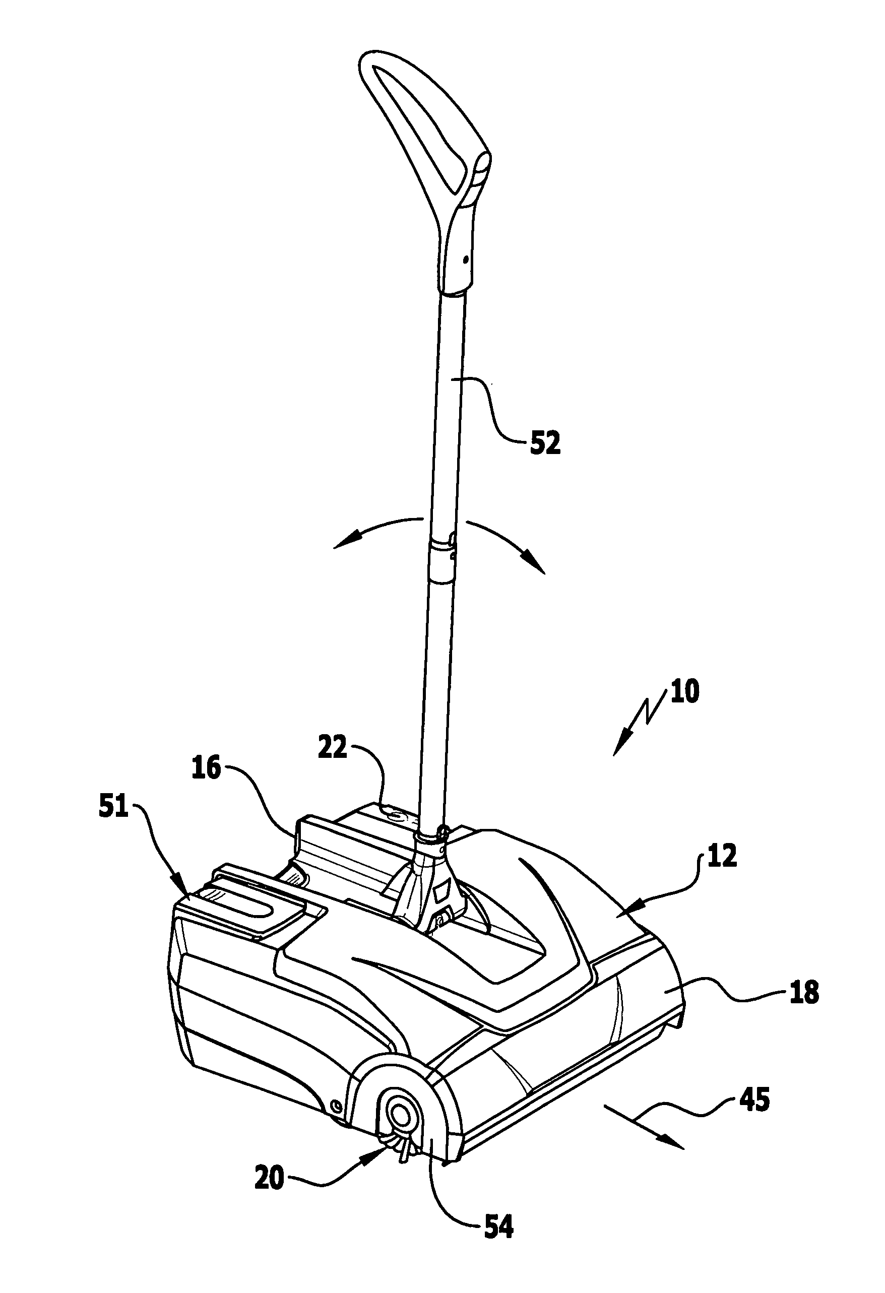
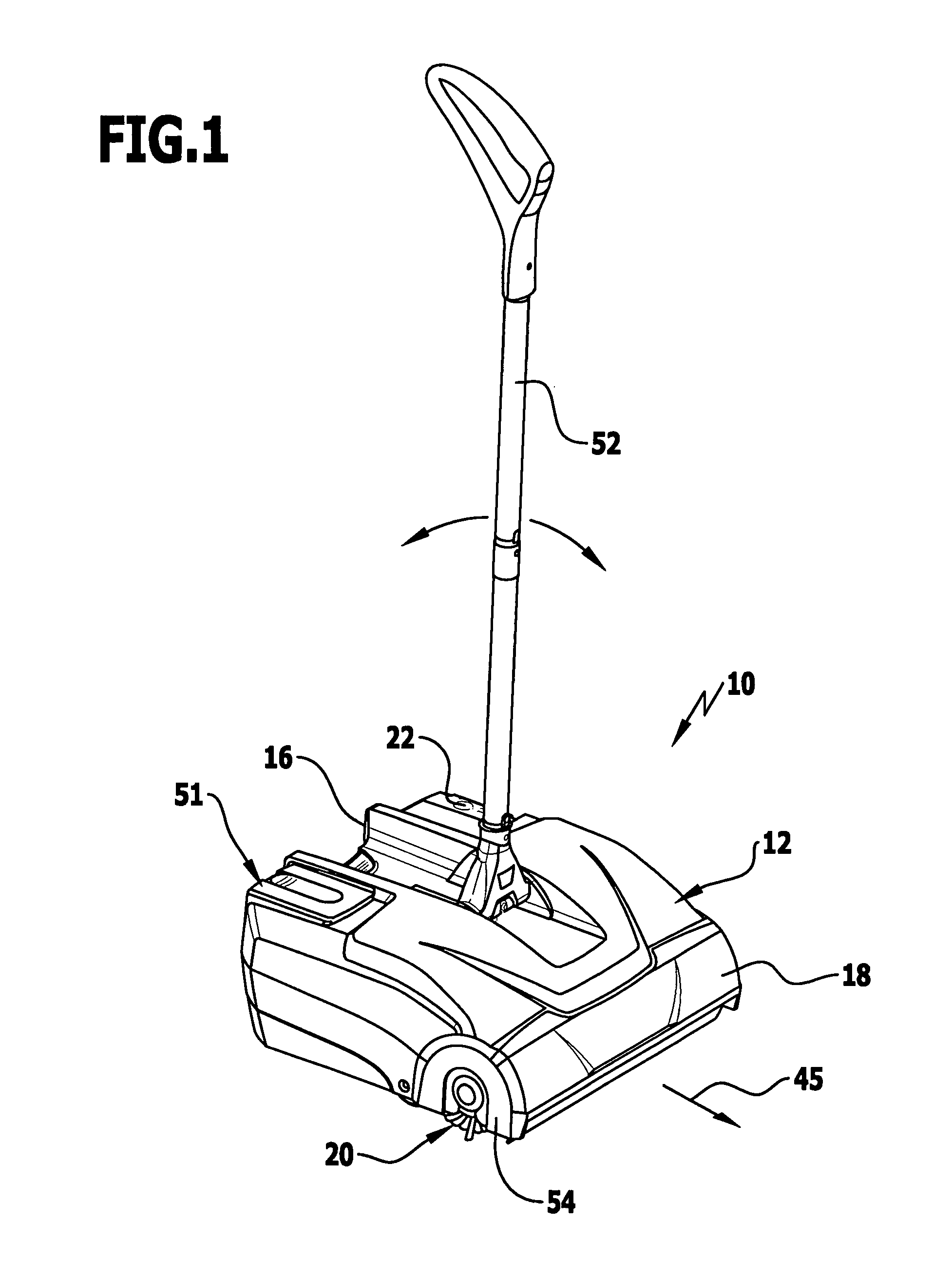
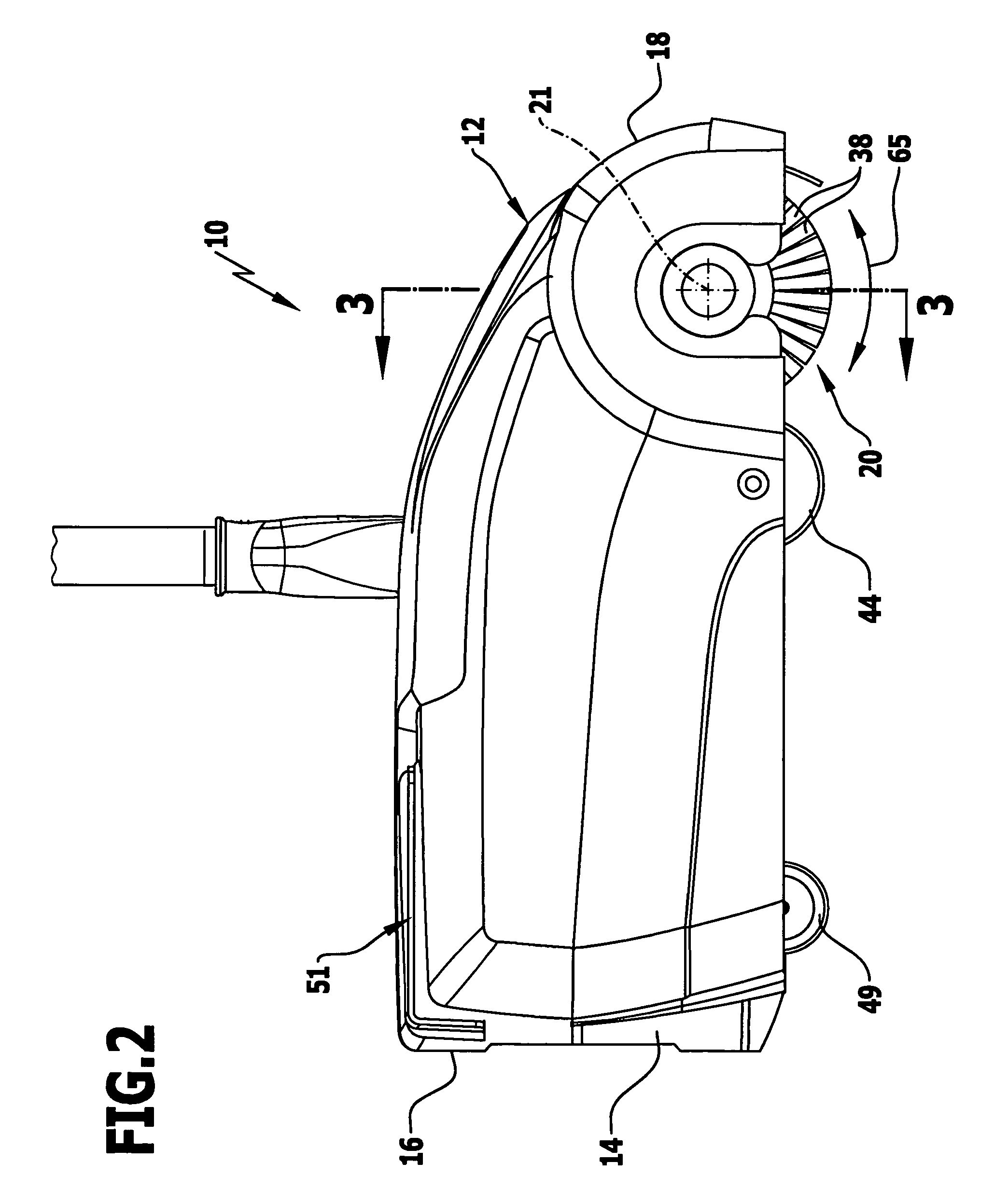
[0027]Schematically represented in the drawings is a preferred embodiment of a mobile sweeper 10 in accordance with the invention with a housing 12 surrounding a sweepings container 14. The sweepings container 14 is configured in the manner of a drawer and can be pulled out of the housing at the rear side 16 of the housing, emptied and then pushed back into the housing 12 again.

[0028]Immediately adjacent to the front side 18 of the housing 12, a sweeping roller 20 is mounted inside the housing for rotation about an axis of rotation 21. The sweeping roller 20 is set in rotation by an electric motor, which is known per se and, therefore, in order to achieve a better overview, is not shown in the drawings. The electric motor is arranged inside the housing 12 in a central region in front of an ON / OFF switch 22. The electric motor is in rotational connection with the sweeping roller via a belt drive 24. The belt drive 24 comprises, as usual, a belt pulley 26, which is rotationally fixedl...


PUM


Abstract

The invention relates to a mobile sweeper comprising a housing, in which a sweeping roller driven by an electric motor is mounted for rotation, and a sweepings container for receiving sweepings, wherein there are mounted on the housing adjacent to the sweeping roller two front supporting wheels and at a distance from these at least one rear supporting wheel, each for rotation about an axis of rotation. In order to further develop the sweeper such that with the occurrence of surface unevennesses, there is no risk of the sweeping roller becoming blocked or of the sweeper tilting, it is proposed in accordance with the invention that the axis of rotation of a first front supporting wheel be arranged coaxially with the axis of rotation of the sweeping roller and, in relation to the main direction of movement of the sweeper, offset from the axis of rotation of the second front supporting wheel.

Description

[0001]This application is a continuation of international application number PCT / EP2009 / 001839 filed on Mar. 13, 2009 and claims the benefit of German application number 10 2008 024 439.2 filed on May 14, 2008.[0002]The present disclosure relates to the subject matter disclosed in international application number PCT / EP2009 / 001839 of Mar. 13, 2009 and German application number 1 024 439.2 of May 14, 2008, which are incorporated herein by reference in their entirety and for all purposes.BACKGROUND OF THE INVENTION[0003]The invention relates to a mobile sweeper comprising a housing, in which a sweeping roller driven by an electric motor is mounted for rotation, and a sweepings container for receiving sweepings, wherein there are mounted on the housing adjacent to the sweeping roller two front supporting wheels and at a distance from these at least one rear supporting wheel, each for rotation about an axis of rotation.[0004]Such sweepers are known, for example, from EP 1 199 971 B1. Th...

Claims


Application Information

Patent Timeline
Patent Type & Authority Patents(United States)
IPC IPC(8): A47L11/32
CPCA47L11/24A47L11/4072A47L11/4036
Inventor WOLF, HANS-PETERSCHICK, ROLAND
Owner ALFRED KARCHER GMBH & CO KG
Why Eureka
Try Eureka