
3D retinal disruptions detection using optical coherence tomography

a technology of optical coherence tomography and 3d retina, applied in image analysis, medical science, image enhancement, etc., can solve the problems of direct impact on disruption detection, error-prone detection methods, and not fully utilized original 3d oct data

Active Publication Date: 2014-01-07
OPTOVUE
View PDF15 Cites 6 Cited by
  • Summary
  • Abstract
  • Description
  • Claims
  • Application Information

AI Technical Summary

Benefits of technology

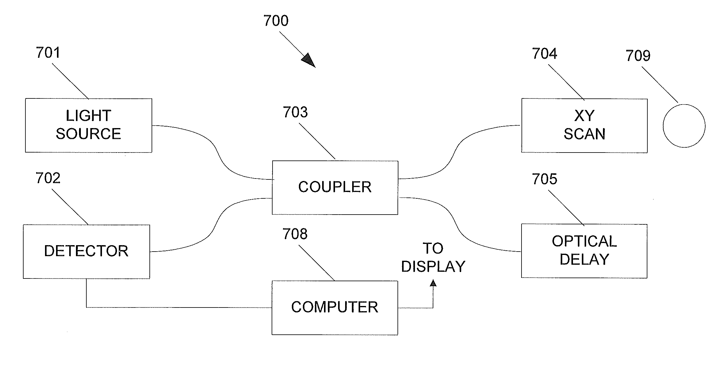
The invention relates to an imaging apparatus and method for obtaining a 3D data set of a sample. The apparatus includes an optical source, an x-y scanner, a detector, and a computer. The method involves processing the 3D data set, identifying 3D seeds, performing image processing to obtain characteristics of 3D disruptions, and displaying the results of the 3D disruptions. The technical effects include improved image quality, better visualization of 3D disruptions, and improved accuracy in identifying and measuring 3D disruptions.

Problems solved by technology

In general, the presence of a disruption is determined by only comparing two 2D surfaces; this means the original 3D OCT data is not fully utilized after the layer segmentations have been performed.
First, such detection methods are error prone because they are highly dependent on results of layer segmentations.
If the 2D surface segmentation is not optimal, the disruption detection will be directly affected and likely produce inaccurate results.
Second, to reduce noise effects associated with OCT data, layer segmentation often employs smoothing operation which can likely introduce the problem of scale.
Excessive smoothing (such as the case with a large smoothing scale) will likely reduce details in desired features, while insufficient smoothing (with a small smoothing scale) will likely be inadequate to reduce noise effectively to generate optimal layer segmentations.
Third, methods assuming constant elevations from segmented layers are less clinically meaningful because disruptions often occur locally with different and unpredictable sizes.

Method used


Image

  • 3D retinal disruptions detection using optical coherence tomography
  • 3D retinal disruptions detection using optical coherence tomography
  • 3D retinal disruptions detection using optical coherence tomography

Examples


Embodiment Construction

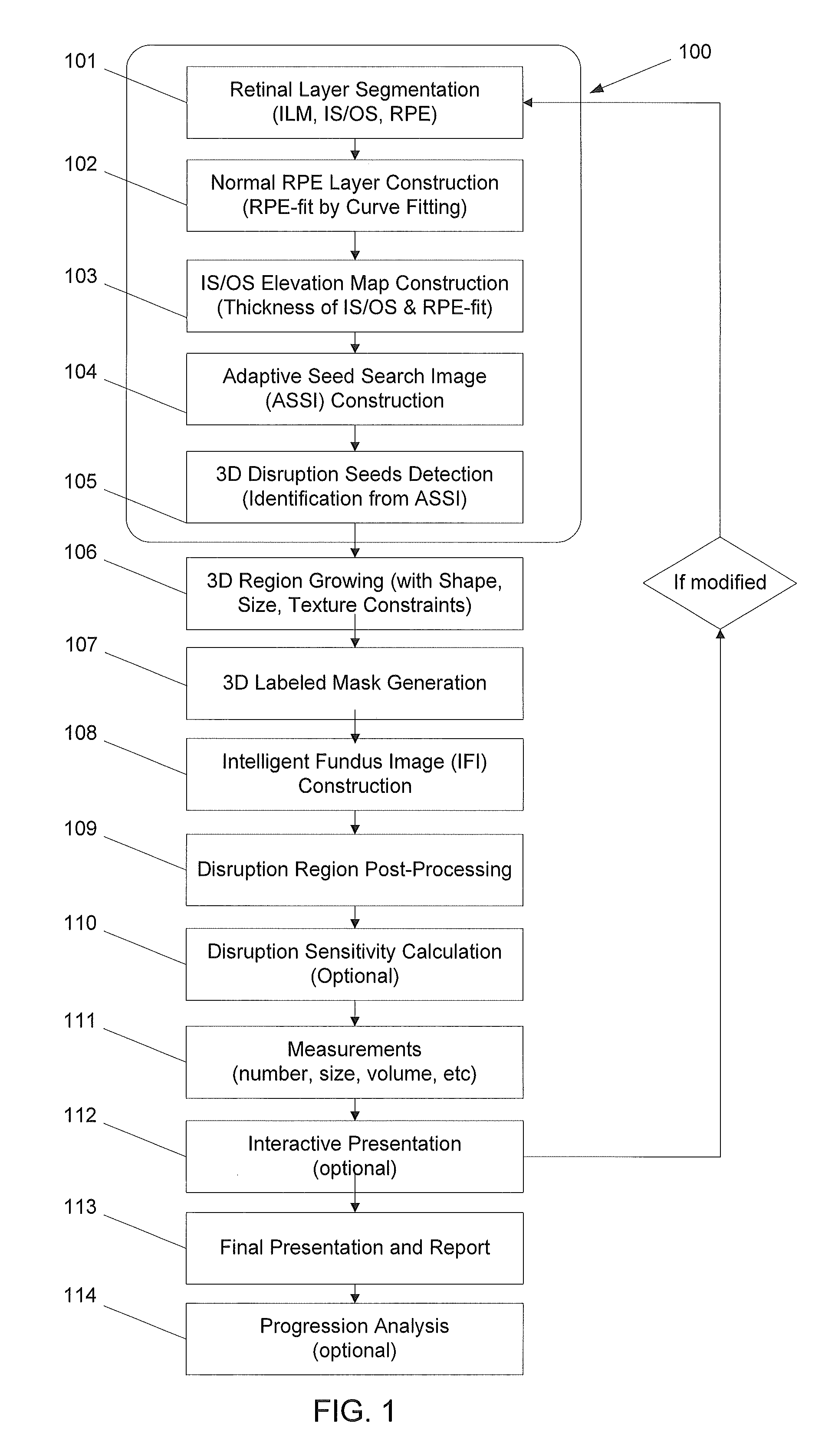
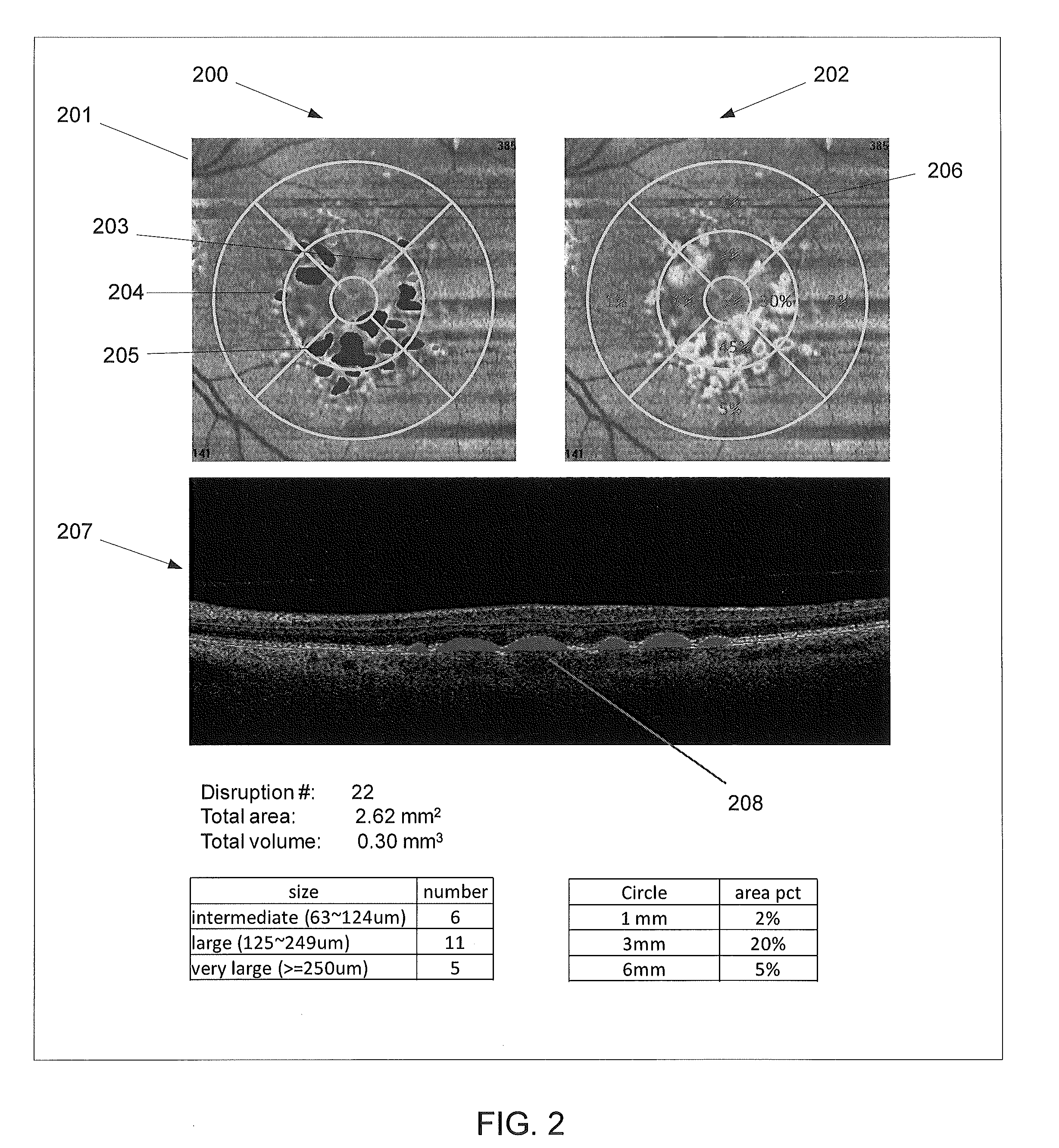
[0024]The aspects and embodiments of the invention disclosed herein relate to a computer-aided detection and measurement system and method to detect and measure the retinal disruption (or elevation), as well as to present the results using the OCT 3D volume data.

[0025]In some embodiments, the retinal disruptions are detected by 3D region growing methods with different constraints, such as 3D shape, size, intensity and texture, 3D labeled mask generation, and Intelligent Fundus Image (IFI) construction.

[0026]In some embodiments, the 3D disruption seeds for the 3D region growing are obtained by a method which contains retinal layer segmentation of Inner Limiting Membrane (ILM), Inner Plexiform Layer (IPL), Outer Plexiform Layer (OPL), Photoreceptor Inner Segment / Outer Segment (IS / OS), and Retinal Pigment Epithelium (RPE) layers, normal RPE layer construction, IS / OS elevation map construction, Adaptive Seed Search Image (ASSI) construction, and 3D disruption seeds detection from all of...


PUM


Abstract

System and method for 3D retinal disruption / elevation detection, measurement and presentation using Optical Coherence Tomography (OCT) are provided. The present invention is capable of detecting and measuring the abnormal changes of retinal layers (retinal disruptions), caused by retinal diseases, such as hard drusen, soft drusen, Pigment Epithelium Detachment (PED), Choroidal Neovascularization (CNV), Geographic Atrophy (GA), intra retinal fluid space, and exudates etc. The presentations of the results are provided with quantitative measurements of disruptions in retina and can be used for diagnosis and treatment of retinal diseases.

Description

RELATED APPLICATIONS[0001]This application claims priority to U.S. Provisional Application 61 / 414,805, filed on Nov. 17, 2010, which is herein incorporated by reference in its entirety.BACKGROUND[0002]1. Field of Invention[0003]The embodiments described herein relates to methods and systems to detect and measure the retinal disruption / elevation of optical coherence tomography (OCT) data, as well as to present the detection and measurement results using 3D OCT data.[0004]2. Background State of the Arts[0005]Optical Coherence Tomography (OCT) has been an important modality for imaging eyes and facilitating ophthalmologists to diagnose and treat subjects with different eye diseases, retinal diseases in particular. The importance of OCT to the field of ophthalmology has also dramatically increased since Fourier Domain OCT (FD-OCT) became commercially available. FD-OCT has much higher scanning speed and higher resolution than the traditional Time Domain OCT (TD-OCT) technologies.[0006]On...

Claims


Application Information

Patent Timeline
Patent Type & Authority Patents(United States)
IPC IPC(8): A61B3/14A61B3/00
CPCG06T2207/20156G06T2207/10101A61B3/102G06T2207/20141G06T7/0081G06T7/11G06T7/187
Inventor GUO, CHENG-ENJANG, BENLI, WENJING
Owner OPTOVUE
Learn More