Targeting an orthopaedic implant landmark

a landmark and orthopaedic technology, applied in the field of orthopaedic landmark identification, can solve the problems of incorrect bone entry point, most time-consuming and difficult steps, inaccurate jig for distal screws, etc., and achieve the effect of reducing radiation exposure of users and patients

Active Publication Date: 2014-01-07
SMITH & NEPHEW INC
View PDF260 Cites 58 Cited by
  • Summary
  • Abstract
  • Description
  • Claims
  • Application Information

AI Technical Summary

Benefits of technology

The disclosed methods and apparatuses have several advantages. Firstly, they can be used without needing X-ray devices to target the implant, reducing patient and user exposure to radiation. Secondly, they allow the implant to be locked at both ends simultaneously, without the need for a separate cannulation process.

Problems solved by technology

Nail deformation during intramedullary insertion, however, may make a jig inaccurate for the distal screws.
In fact, the positioning of the distal locking screws and alignment of the drill for the drilling of the distal screw holes is the most time consuming and challenging step of the implantation procedure.
The two main reasons for failure in distal locking are (1) incorrect entry point on the bone and (2) wrong orientation of the drill.
An inaccurate entry point also compounds the problem as the rounded end of the drill bit often slips, damaging healthy bone rendering it difficult to place another drill hole next to the inaccurate hole.
Inaccurate distal locking may lead to premature failure with breakage of the nail through the nail hole, breakage of the screw, or the breaking of the drill bit within the bone.

Method used


Image

  • Targeting an orthopaedic implant landmark
  • Targeting an orthopaedic implant landmark
  • Targeting an orthopaedic implant landmark

Examples


Embodiment Construction

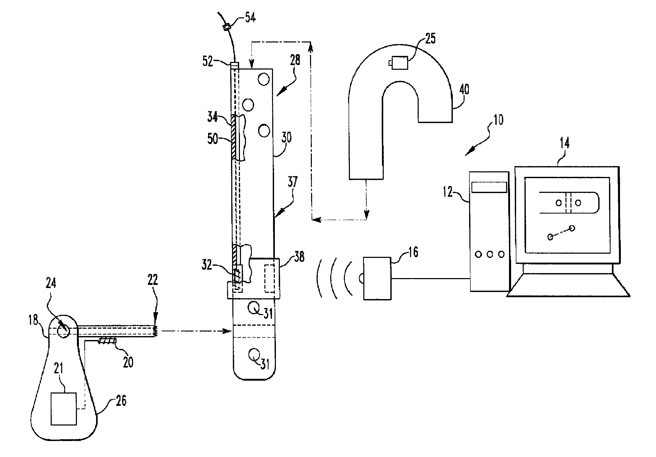
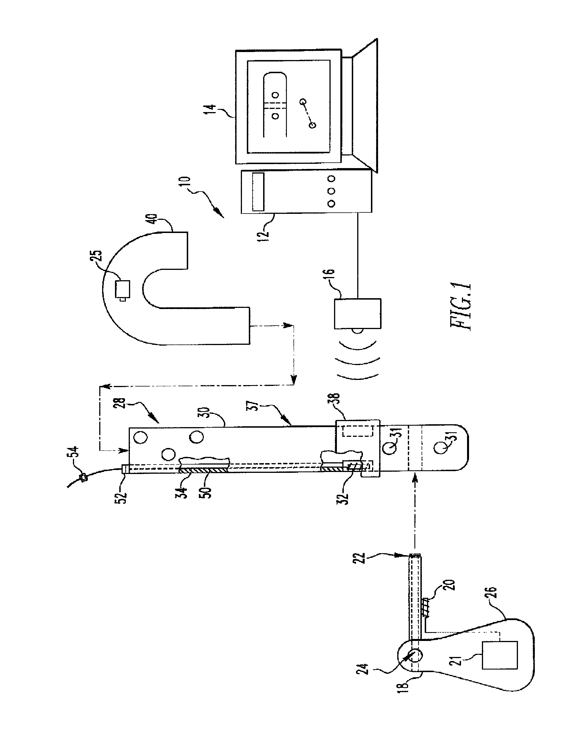
[0084]Referring to the accompanying drawings in which like reference numbers indicate like elements, FIG. 1 illustrates one disclosed system 10 for identifying a landmark. The system 10 may include a processor 12, a magnetic field generator 16, a landmark identifier 18, and an orthopaedic implant assembly 28. The system 10 may also include a monitor 14 electrically connected to the processor 12 and an insertion handle 40 removably attached to the orthopaedic implant assembly 28. The processor 12 is depicted as a desktop computer in FIG. 1 but other types of computing devices may be used. As examples, the processor 12 may be a desktop computer, a laptop computer, a personal data assistant (PDA), a mobile handheld device, or a dedicated device. The magnetic field generator 16 is a device available from Ascension Technology Corporation of 107 Catamount Drive, Milton Vt., U.S.A.; Northern Digital Inc. of 103 Randall Drive, Waterloo, Ontario, Canada; or Polhemus of 40 Hercules Drive, Col...


PUM


Abstract

A system for targeting landmarks on devices such as surgical implants is disclosed. The system can include a field generator for generating one or more magnetic fields, an orthopaedic implant located within the magnetic fields, the implant having at least one landmark, a removable probe with a first magnetic sensor, a landmark identifier and a processor. The landmark identifier can contain a second sensor, or, alternatively, the field generator. The processor can utilize sensor data and, if desirable, field generator and other information, to generate and display the position and orientation of the sensor(s) in preferably six degrees of freedom, and thereby, to generate and display the position and orientation of the landmark(s). The system allows for blind targeting of one or more landmarks. The landmark identifier, field generator and / or drill motor may be disposed in an autoclavable housing.

Description

CROSS REFERENCE TO RELATED APPLICATIONS[0001]This application is a continuation of U.S. patent application Ser. No. 12 / 758,747, filed Apr. 12, 2010, which is a continuation-in-part of U.S. patent application Ser. No. 12 / 547,716, filed Aug. 26, 2009, which claims priority to U.S. Provisional Application No. 61 / 173,069, filed on Apr. 27, 2009. The entire contents of U.S. patent application Ser. No. 12 / 758,747 and U.S. Provisional Application No. 61 / 173,069 are incorporated herein by reference.BACKGROUND[0002]1. Technical Field[0003]This disclosure relates to identification of blind landmarks on orthopaedic implants.[0004]2. Description of the Related Art[0005]The interlocking nail has significantly widened the scope for intramedullary (IM) fixation of long bone fractures. Anchoring an IM nail to a bone makes the construct more stable longitudinally and stops rotation of the nail within the bone. A typical IM nail fixation surgery involves a combination of jigs, x-ray imaging, and manu...

Claims


Application Information

Patent Timeline
Patent Type & Authority Patents(United States)
IPC IPC(8): A61B17/56
CPCA61B17/1725A61B5/1127A61B5/06A61B5/05A61B17/1707A61B2019/5251A61B2019/5272A61B2019/4868A61B2034/2072A61B2090/0813A61B2034/2051A61B5/062A61B34/20
Inventor RITCHEY, NICHOLAS S.SCHWAGLI, TOBIAS
Owner SMITH & NEPHEW INC
Why Eureka
Try Eureka